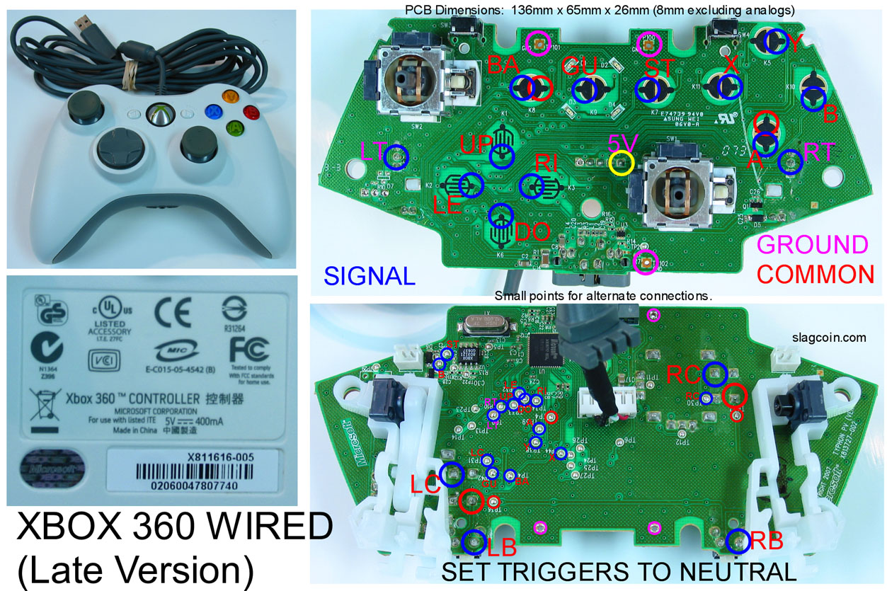
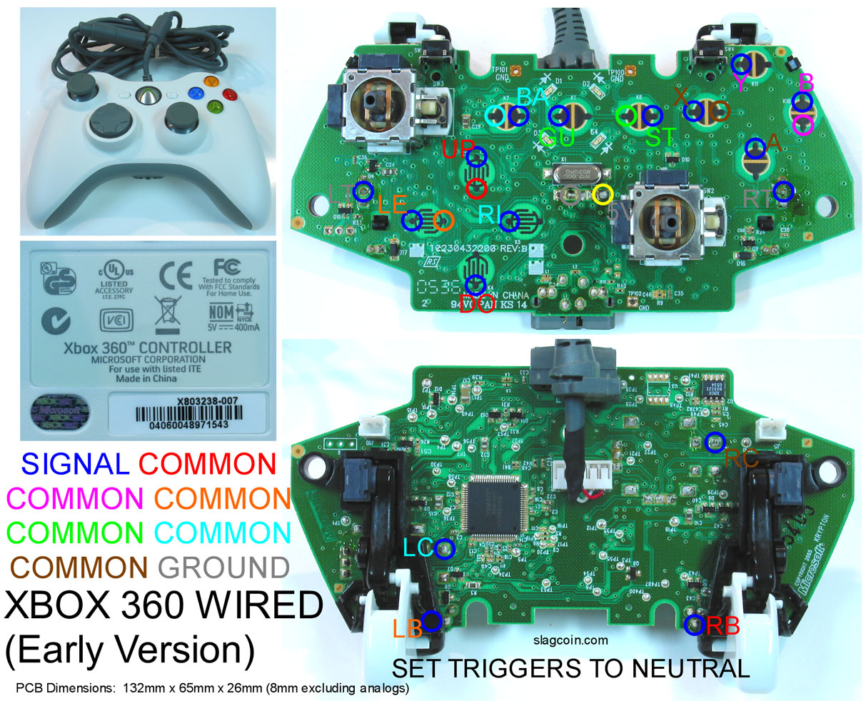
So I’ve got an older style pad with no common ground and a newer pad with a common ground. What would be better to use?
^Thats the new pad. When I’m hooking up a JLF would I just put the ground to one of the 3 purple circles? Then the buttons would connect them all to one of the the common grounds(A,B,X,Y,Back,Start, Guide goes to the ground by A or Back)?
^Thats the old pad. For that one I’d have to connect 2 buttons to each common(X and A would both connect to the common by X?). And the JLF PCB would have to be grinded down so the traces are torn?
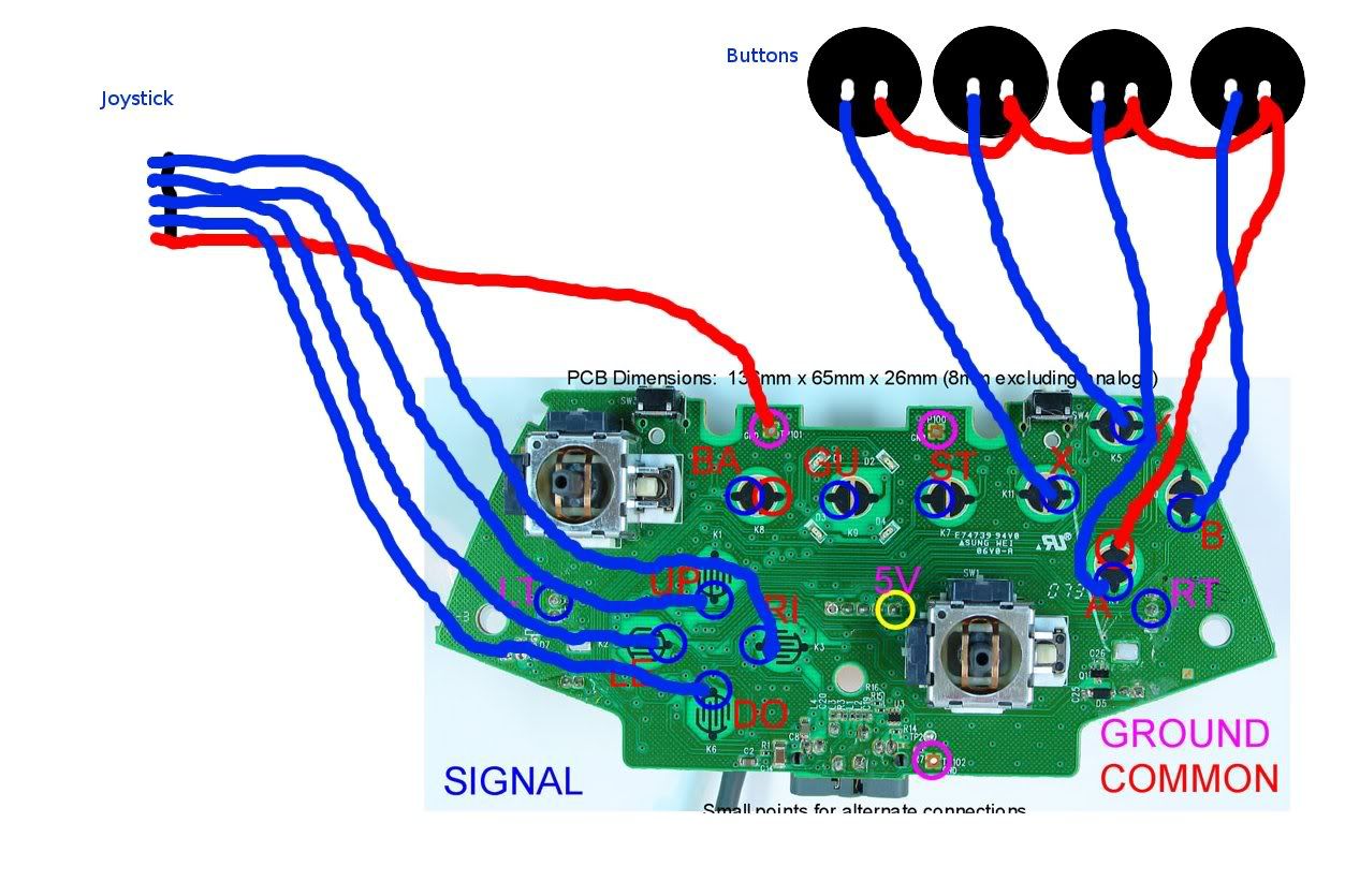
Does anyone have a pic of the new PCB already wired up. Maybe that will help me out.
honestly though, 1st party 360 pads are not only difficult to hack, but aren’t very durable, there’s not really anywhere for the solder to grab on some points
i would just stick to a madcatz. they’re easier to hack, and cheaper
What do you mean go with the common ground? Is what I showed in the picture correct? DO you mean move the button ground to one of the purple circles instead of the red one?
I’ve never hacked a pad but I’ve installed modchips and the like so this will be pretty damn easy for me as long as I understand how where to install everything to.
Have you ever seen some of the Wii contacts you need to use for a chip? Shit son, one contact on these PCBs are bigger then all the Wiis put together.
i meant use the common ground controller, the one thats not is double the nightmare that the later version is
what about your bumper buttons? also, that pic is bigger than the actual pcb, and further more, there is next to no copper in those contacts, if you fuck up on one cantact, thats it, the pcb is toast
believe me man, this shit is tedious, i just don’t want to see you ruin a pad, cause i’ve ruined like 3
I don’t have them all mapped on the pic, I just want to know if thats the right idea. I.E connecting all the grounds on the button and connecting them to that common spot then the signals to each signal. And the joystick to the ground and the signals to the signals.
As for soldering to the contacts, I have already said that is no problem. If I mess up a contact(doubtful) I will just solder to the trace, if I mess up the trace I’ll just solder to the via. It’s not a big deal. Really. I’ve been soldering for years. You should see the Wii mods I do if you want to see some crazy soldering.
ok well you’ve got the right idea, and you seem to be more experienced than i in soldering
good luck, test all of your buttons when you are done, and if they all work, HOT GLUE THAT SHIT! even with glue and a well done solder job my shit fell apart