First of all, this isn’t Krost - this is his brother. I made a previous thread (2 PCBs in one stick- Possible?) and learned so much that I now do this often as a hobby.
I’ve recently tried hacking a MadCatz “Joystick” (the small cheap PCB used to play games like Pac-man and similar games) and was almost successful. I used the bumpers instead of the triggers with success, and was able to wire up my brother’s (Krost) controller. It seemed to work fine, but he had problems with the controller randomly spamming a random button. For instance - he would play for an hour, and out of nowhere his controller would start jumping up over and over again until he unplugged the controller and plugged it back in.
I did follow directions after reading a few threads on how to “neutralize” the triggers using resistors. I don’t have the specific parts that I used off the top of my head, but I did solder the correct contacts as per the diagram on slagcoin. I read that the direction that the resistor is “facing” doesn’t matter - I’m assuming this is true for the rest of this thread.
I’m about to start from scratch with one of the MadCatz controllers (The ones they sell at GameStop) and will look over the diagram on slagcoin beforehand. I have the following questions about deaing with triggers that I can’t seem to find a definitive answer for:
If I’m not using the triggers, do I just leave them “as is”? For instance, they have a big hunk of plastic with a spring and all that the actual trigger uses to change the signal on the PCB. With the Playstation Dualshock controller, I’ve read just to hot glue the analog sticks to make sure they don’t accidentally get activated. Should I do something similar with the trigger assembly?
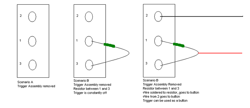
If I were to remove the trigger assembly completely without “neutralizing” it with a resistor, what can/should I expect to happen? Assuming that I’m not going to use the triggers at all, should I worry about it?
And for the sake of future use of the thread, if anyone could post some detailed pictures of how to neutralize the triggers, that’d be great. I know it’s done in other threads, but I found looking for information on this subject cumbersome as bits and pieces are spread out into multiple threads with many pages in between.
This has been asked (and answered) many times before, but because I’m nice (and also because the search is disabled :rolleyes:) I will help you out.
If you have room in your stick, leave the triggers alone, you don’t need to glue anything. I mean, what is going to trigger them in the box??
If you want to remove the triggers, you will need a couple of 10k resistors to solder in place of each trigger otherwise the controller will do weird things, like trigger randomly and other crazy stuff.
This thread here should help you out of where to solder the resistor. It is for the M$ pad, but the process is basically the same for the Madcatz pad.
For the record, I do look at the posts before posting. However, this specific topic wasn’t covered in detail as far as I could see. I’m sure it’s somewhere on this forum, but I wasn’t really in the mood to click through 40 pages to find it, and I’m sure this question will be asked again in the future. I made the topic pretty specific so that others will be able to get their answer from this thread easily.
Anyway, like you said, it’s a Microsoft controller, but hopefully the MadCatz boards correspond to the same pin numbers for the triggers.
(Before I get lynched) I tried using the search button on that thread you linked, but it didn’t work. Could someone help with naming the pins? LT1/LT2/LT3 is great and all, but can they be labeled so I can make some sense out of how this is working?
For instance, LT1 = ground LT2 = etc…
Thank you for the help.
Edit: Also, come someone tell me if these assumptions are correct?
I just noticed that wouldn’t work for the last scenario - the wire has to be connected to the 1 pin.
What did you find out Ryan? I am hacking a new style Madcatz #4716 right now. I havent finished as I just started last night. The thing is I did in fact remove the triggers, safely, screws and all. Do I have to solder a 10 k resistor now??
I just hacked a GameStop/MadCatz pad (one of the pointy ones, with the new common ground pcb) and I accidentally ripped one of the trigger pots clean off the board while removing the trigger assembly. It’s not triggering anything at all as far as I can tell. I’m wondering with that 4716 2008 pcb if you can just remove them altogether and be done with it. It seems to be working.
In the end, I found that the best way to locate what pots you need to apply resistors to is to look at the board. One of the pots is going to be the ground - the other one is going to be signal and voltage. If you can find the one that is the ground, then you just have to stick a 10k resistor between the other 2. If you rip a pot off the board, just follow the trace and hopefully you should be able to find another point to solder to. I ripped a pot off on both sides, and I was able to find another spot to solder to.
When I originally soldered my first 360 controller, on one side, I put the resistor on the ground and one of the other pins. It worked for a while, but it would randomly start spamming jump or heavy kick. Once I looked at the traces and found that it was the ground, re-soldering the resistor to the correct points fixed the problem for good.
So, disregard the picture I posted and just look at the board’s traces, find the one that’s not the ground, and solder those bad boys on. The orientation of the resistor doesn’t matter, FYI.
I have no idea how to find out which of the holes is ground and which are the others. Only the top hole has a path to it while the others don’t seem to have any (on this side anyway).
For the older MS pads (the one with TP3 on the bottom left of the battery springs, the same one in the picture below) which of the holes is correct?
so for madcatz 4716 pads 2008 and later, removing the triggers needs no resistors, you can just take them off and leave them be if you’re not going to use them?