Three questions guys.
1. So I have 2 of those early Matrix wireless PCB’s and I want a wireless stick. From what I understand, it is still possible to use this PCB, it’ll just take a little more work.
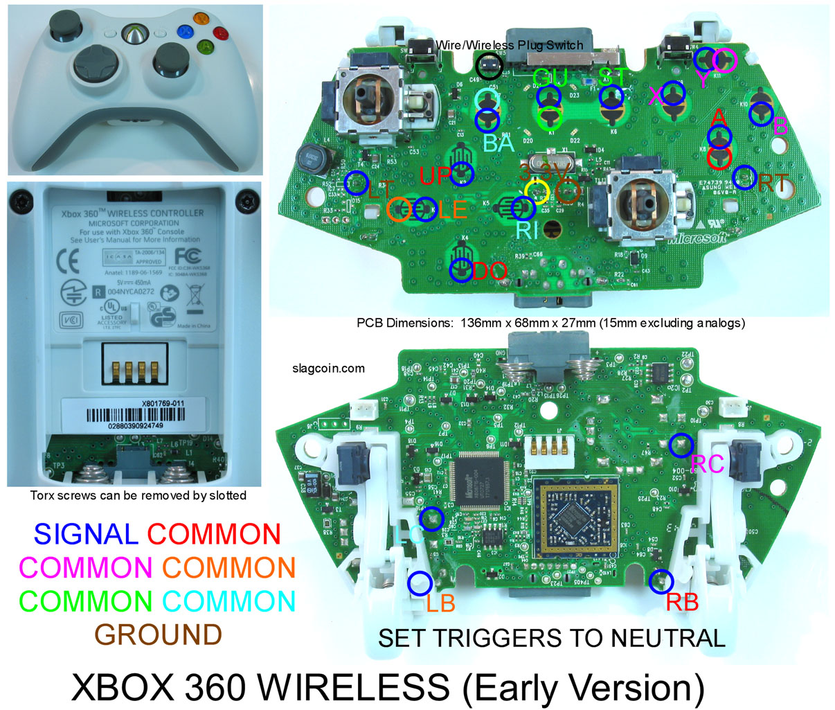
I checked slagcoin and found the diagram for this PCB:
Xbox 360 wireless (early version)(Matrix?)
Since this isn’t a CG PCB, I originally thought you would have to wire 2 wires per button on the PCB but after studying the diagram, it looks some of the buttons share a ‘common’.
example:
Looking at the signal points for X, B, and Y, notice the letters are labeled in purple while the solder points for the respective X, B, and Y are in blue meaning this is where you get signal. There is also a ‘common’ solder point in purple near the Y signal point. Please tell me my understanding is correct.
X, B, and Y’s signal come from the blue points from the PCB, then go to their arcade buttons where they are shorted and then can be daisy chained (X, B, and Y only) into the purple ‘common’ on the PCB.
If this is true than does that mean I don’t have to run two wires per button on the PCB, instead just daisy chain a specific group of buttons to their respective ‘common’?
2. Also, I read on Xbox scene that the triggers on these PCB’s are independant from the rest of the matrix. So does that mean I could just put a 10k resister between T1 and T3, and then short the arcade button between T1 and T2?
3. Reading around SRK, it looks like alot of people with wireless 360 sticks don’t even use a sync button b/c when you hook up a usb to charge the battery, it automatically sync’s the PCB to the Xbox. Is this true for all wireless 360 PCB’s?
Thanks ahead of time guys, I know I could avoid all of the extra work by going the wired route or even getting a CG wireless controller but I don’t want to spend any more $ plus I think I’m up for the challenge.
Thanks again guys!
