Universal PCB (eventually) thread

Sorry for the newb question but i can’t seem to find anything that has answered my question on here. I am trying to get a custom pcb specifically for a PS3 arcade stick. Is the UPCB the way to go? I have almost non-existent programming skills. I can solder though. To be honest i don’t fully understand how the UPCB works anyway. Could someone please explain? Thanks.

Jaty

You want the cthulthu
http://forums.shoryuken.com/showthread.php?t=162026

Sounds like you need a Cthulhu, no programming experience needed at all. Read through the Cthulhu thread, especially the first post.

Ok toodles, major problem.

My pre-assembled UPCB has a short in it. I have 0 resistance when i take my multimeter to ground and vcc test. This is with nothing plugged into it at all. Help.

Hi Toodles, I downloaded the UPCB_25 source code so I can play with it and learn some microcontroller programming. I had no problems building/compiling the code in MPLAB IDE v 8.1(it came with pickit2 debug express kit) and the academic version of the C18 compiler. The problem is that when I try to program the demo board
(PIC16F887 onboard) with the pickit2 v2.5, I get the following warning

"No configuration words in hex file. In MPLAB use File-Export to save hex with config. "

Could this be due to the fact that I should use the programmer within MPLAB IDE? Currently I have Programmer->select programmer->none in MPLAB IDE.

Most importantly however, do I need to make any setting changes to MPLAB IDE before I can build/compile the UPCB_25 code and program it onto the chip? I’m new to all this so I don’t know if I have everything set up correctly.

I also noticed that pcusb.h was commented out. I was wondering if that means pc is not supported with UPCB_25?

Many thanks for making the source code available, I learnt a lot thanks to it
fes

Hi,

since Toodles opens all informations needed to reproduce his UPCB we’re proudly present the first batch in germany.

Current state is:

  • All parts are ordered
  • PCB are produced and available.

TODO:

  • Testing (will end hopefully next week)
  • Programming Pics (no clue :wink: )

Here some pics

Higher resolution

I will keep you informed about news. Of course we’ll taking orders, but first we need some testing.

Bye,

bencao

I finally got my parts in for making the UPCBs. I have a few issues that I need to solve before I start the process:

1.) I’m going to use the piggyback method for DC and X360 support. Is there a specific controller that you would recommend? [I heard from the “padhacking” thread that there are some out there that don’t have common ground and/or lags] I haven’t had much success in finding a DC Agetec PCB.

2.) Also, Do you know of a good place to buy them from? [amazon, trading outlet, Gamestop, etc.]

3.) How much will you charge for shipping if I choose to ship my PIC cards to you for programming? [zip code 99506]

Thanks for the assistance.

First one ready assembled. Can’t await to test. First batch is about 30 pieces

higher resolution

Hi,

tests was successful. Test report can be found here.

The red one is the new produced UPCB.

Dreamcast Piggyback

xbox360 piggyback

We’ve a large batch and ready to reproduce more of them. Feel free to contact me by pm to order.

Bye,

Bencao

bencao,
The label on the chip said UPCB 2.50. You are making sure you get the BOOTLOADER.hex programmed onto the new chips, yes? The regular UPCB .hex’s don’t include the bootloader.

Yes, first the PICs was programmed with the bootloader (with a normal pic programmer).

Next step was to put the PIC on the UPCB board and update the firmware with the programming usb cable to ensure all is fine.

Okay, this was two steps for programming but it was quite affordable for 30 pieces.

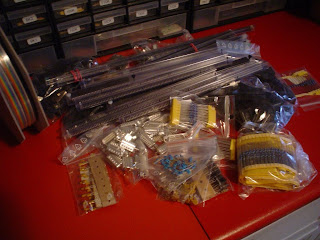
Hi Toodles, I ordered the exact parts as specified on your UPCB assemble tutorial on www.instructables.com. Currently I am having trouble getting the sanwa JLF to work on the breadboard. Before I describe my problem in detail I’ll just briefly go over what I have done.

  1. I made minor changes to your v2.5 UPCB code. I made changes to main.c.

I deleted all the code that deals with determining which consolde the pcb is connected to and set ps3 as the default. This is what “void main(void)” looks like now.

void main(void)
{
/* Set all of the console pins to input, as well as the button & stick
pins, using the macros from upcb.h. The console pins used for output
will be set as needed in those system’s main routine. For now, we want
everything nice and safe as inputs */
ADCON1 |= 0x0F; //set all input as digital.
mInitAllLEDs();
mLED_1_Off();
mLED_2_Off();
mInitConsolePins();
mInitButtons();
mInitStick();
//Init_Piggyback();

	mLED_2_On();
	Program_Load_Mappings(SMA_USB);
	PS3USB_main();


	// if we get here to the end, we haven't matched any of the supported controllers
	// so sit and spin and wait for a replug
	mInitAllLEDs();
	mLED_1_On();
	mLED_2_Off();
	while(1)
	{
		Delay10KTCYx(250);
		Delay10KTCYx(250);
		Delay10KTCYx(250);
		Delay10KTCYx(250);
		Delay10KTCYx(200); // at 12 MIPS, 1.2mil cycles augh to = 1 sec
		mLED_1_Toggle();
		mLED_2_Toggle();			
	};
}//end main
  1. Linker Script rm18f4550.lkr was used (could this be the problem since I’m not using the bootloader but programming the PIC microcontroller directly from MPLAB IDE)?

  2. I compiled your code with MPLAB v8.1 with academic version of C18 compiler. I programmed the chip with a modified PICKIT2. (This modified programmer from www.auelectronics.com allows you to directly program a PIC on a breadboard). From within MPLAB IDE with the newly compiled hex loaded, Programmer->Select Programmer->PICkit 2.

  3. Here is a diagram of how I arranged the parts on the breadboard.

http://img9.imageshack.us/img9/5825/breadboardsetup2k.jpg

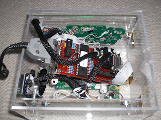
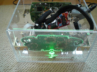
  1. Here is a picture of my board and the parts on it
    (http://img24.imageshack.us/img24/289/pictureofbreadboard.jpg)

Having done all the above, I am able to connect to the PC and PS3. Both platforms have no trouble recognizing me pressing the ‘SHORT’ or ‘START’ button.

The problem I have now however, is that I cannot get the Sanwa JLF joystick to work. After connecting all the wires to the breadboard and connecting to the ps3 or pc, I see that the upcb is giving off random left, right, up, down commands at rapid succession with the joystick in neutral position! I’m not doing anything to it yet It seems as if someone is doing 360’s like mad. I then removed all the wires but left the black (ground) and green(right) wire connected. I noticed that the upcb would then behave as if I pushed right on the joystick and held it there. I really have no clue what is happening and desperately need your advice. Please help me ^^

One more thing, the 4 resistors that sit between the PIC microcontroller and the 4 joystick wires are
Digikey#4.7KQBK-ND, the same ones I have sitting between the sanwa buttons and PIC microcontroller. Could I be using the wrong resistors?

P.S. I notice that the upcb is very unstable. It would disconnect from my computer when I get up from my chair, or when I place my keyboard next to it (the bread board is placed on my desk). It seems as if the shocks caused from just walking near it causes it to connect and reconnect lol. Could this be due to the fact that the legs of the crystal/resistors/capacitors are too long?

Thanks in advance.
fesodes

If there’s no pull up resistors, then the inputs are floating; there is nothing to bring the voltage on the input up when the stick is in neutral.

Beats me. Please dont say the upcb is unstable; its not. You doing an incomplete implementation on a breadboard, that may be a little shaky though :slight_smile:

Thanks a lot for your reply Toodles :smiley:

“If there’s no pull up resistors, then the inputs are floating; there is nothing to bring the voltage on the input up when the stick is in neutral.”

Thanks to your advice I think I found the problem. I rechecked the Universal PCB Schematic - Toodles 2007 Rev 2.0 and noticed that up, down, left, and right are all connected to VCC. I also did some research on the internet and found the following diagram that allowed me to better understand what is happening.

In my previous implementation, VCC was not involved in the connection of the joystick and thus when the switch is open(sanwa in neutral position), the signal would be zero, left floating. Thus I need to add VCC to the picture such that when the switch is open, the signal is connected directly to VCC. I also need to have a pull up resistor in place to prevent VCC and GND connecting together. The below diagram is what I think I need to do to get ‘RIGHT’ of the joystick to work.

http://img258.imageshack.us/img258/8533/breadboardsetup4.jpg

But before I do so, I want to confirm with you first because I don’t want to accidently fry my components and have to buy them all again in the event that I misinterpreted. Of most concern to me is whether the 4.7k resistor(Digikey#4.7KQBK-ND) is the right part.

Oh and I want to add that the upcb is great. When I said my upcb was unstable, what I was referring to was the result of my crude arrangement/implementation of the upcb on the breadboard. I loved the upcb and had a lot of fun while putting it together and learning how it works. I want to thank you again as it wouldn’t be possible without you.

Sincerely
fesodes

Hi Toodless, I have problem with xbox 360 piggyback. When I plug UPCB, buttons 1 to 8 are pressed. When I press a button, the button change state tu un-pressed.

All buttons have the same problem and the four directions doesn’t work at all.

I use new official xbox 360 pad. All buttons have common ground but this ground his not common with the usb ground.

Is there a solution for this problem ?

Thanks a lot…

I’m in the process of soldering the parts onto the 2.1 UPCB board, but I’m having an issue: I don’t know whether or not to solder on the 4.7 ohm pull-up resistors or not. The pic @ the bottom of Toodle’s 1st post in this thread shows that thos areas are for 10 ohm resistors, but the excel schematic shows that it’s for a 4.7 ohm resistor. Which way is the right one?

That’s a contradiction. All of the signal may share a common, but the common is not ground. Not common ground, it won’t work. Use a common ground pad.

You’re missing the ‘k’ which makes a big difference. :slight_smile: Big diff between 4.7 ohm and 4.7k ohm.

But to answer your question, the ones marked 10k ohm on the picture in the first post are just pull up resistors, and you can use damn near any value resistor you want as long as it’s high. If you have 4.7k ohm resistors, you can and should use them in all of the spots marked 10k ohm in the picture on the first post.

Thanks for the help!

I’ve made a usb button select cable tested and working on PC and PS3. however, I can’t get the usb button select cable to work with my xbox1.

  1. can the usb button select cable be used with xbox1 (with the appropriate adapter)?
  2. if so, do I have to hold down certain buttons to make it work?
  3. where can i find more documentation on the button select cable i.e. what are all the button combinations to hold down for all the functions?
  1. Yup.
  2. Yup.
  3. There’s a post where I laid them out. I found the post, but only in a google cache, so I can’t find the damn post number :frowning: But, I’ll copy and paste it to the first post, and right here: