Hey guys and gals,
This is a simple tutorial on how to connect your Madcatz TE button and joystick wiring to a db15 connector for easy swapping of control panels.
Well lets get started,
first you must completely remove your control panel, there are tons of tutorials on how to do that so i wont bother with that portion. Once your control panel is removed, locate your pcb and unscrew it from the case. After you unscrew the 4 screws flip the pcb over carefully and be careful not to force anything. It is not necessary to remove the wire harnesses but you may want to as to avoid any problems.
Here are the points you will be looking at for this mod
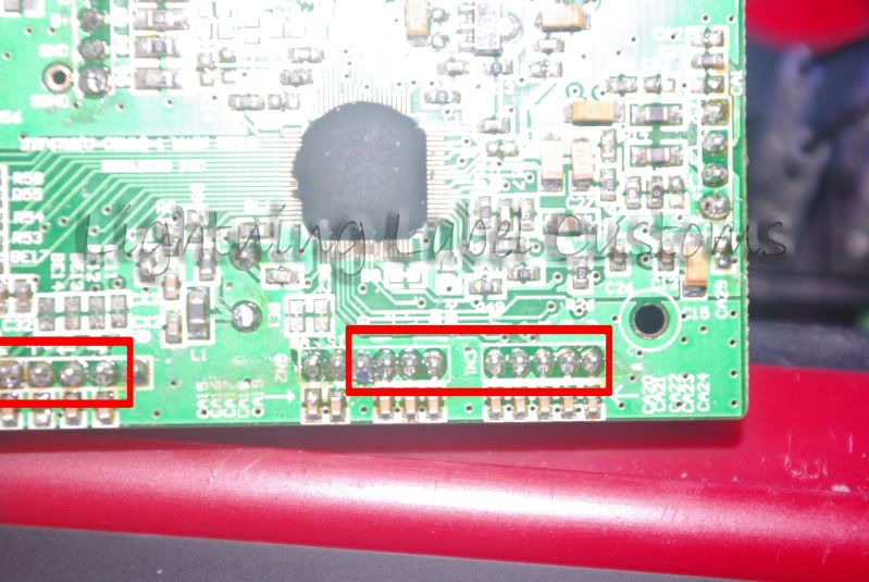
there are 13 points total.
8 Button 4 directions and 1 ground
These points are already conveniently labeled so it is much easier to know which signal you are soldering.
Now go ahead and cut your 13 wires, remember it is always better to cut wires too long than too short, I used 26GA(white) and 24ga(black) wires.
Solder each wire to the pcb, you should have something similar to this when done
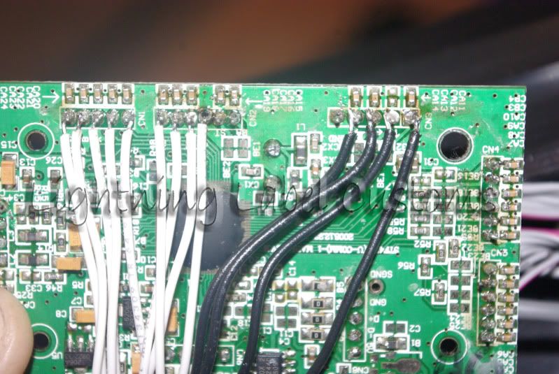
After you have made sure all of your wire connections are secure and good to go, it is time to test.
It is not necessary that you test but it would save alot of troubleshooting time later if something went wrong
You can test on your computer or your console. Just tap each signal wire to the ground wire to make sure you get a proper response.
Once everything is tested it is time to connect your wires to the db 15 connector.(male)
The type i am using has 3 rows
Sorry i forgot to take a pic of it beforehand but i have a pic of it with all the wires connected. It doesnt matter which type you use as long as you get the matching connector to plug into it
Before soldering your wires to the db15 connector it would be best to have an outline of which wire is going where but to make things easier here is the way i will wire mine, you can do the same that way you will always be able to have a diagram to refer to
Here is how The db15 connector is wired
Top Row from left to right
A B X Y LB
Middle Row from left to right
RB LT RT Ground Empty
Bottom row from left to right
Right Left Up Down Empty
**Note that if you plan on ever using an optical stick, one of the empty spots will have to be the VCC
Now that everything is planned out it is time to solder those wires up.
Here is a pic of it all wired up.
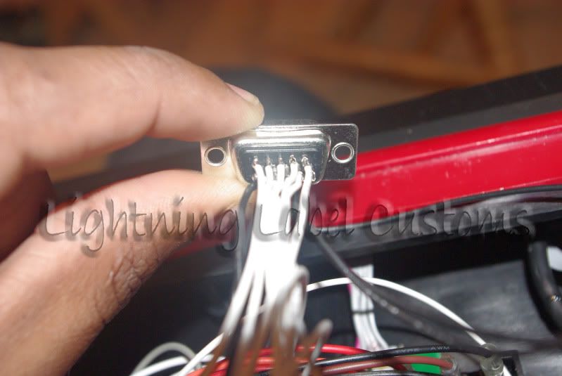
As you can see you will have two open spaces, if you wanted to you could wire start and back/select to those two but the way this tutorial is showing you how to wire will still allow you to use the wire harnesses so you can still use the wires for start and back/select. The reason I chose not to wire the start and back/select buttons is because those buttons are not on the control panel, unless of course you ordered
a panel with those buttons but you could still simply connect the wires to those buttons.
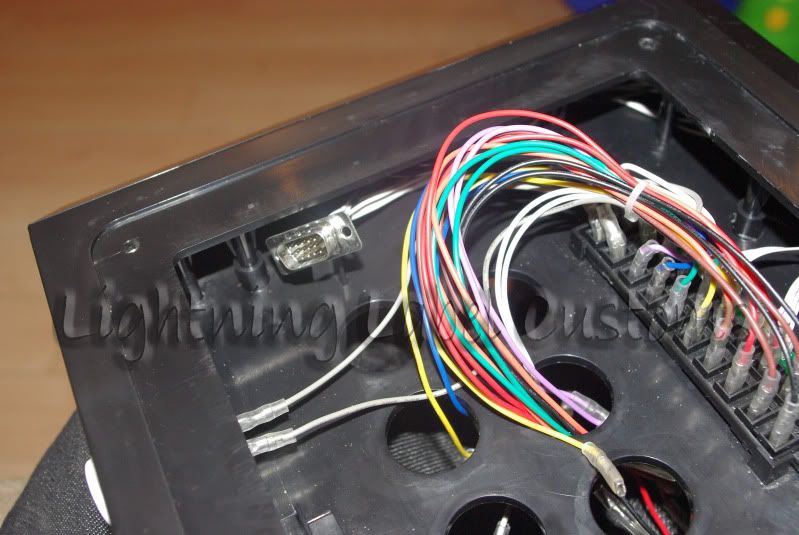
Now all thats left is to put the connector back into the case, I ran the wires behind the poles or legs in the case. It keeps all the wires out of sight and out of the way/
Here are some pics of the connector in the case
Here are the wires coming out the back of the Madcatz PCB
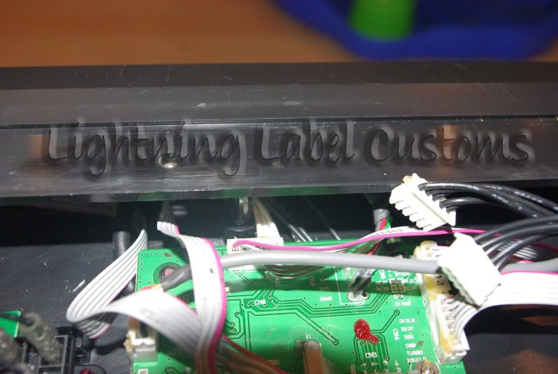
Here it is in the case
Now for the second part, Wiring your panel to a DB15 connector(female)
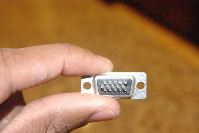
The important thing to remember is that everything is going to be reversed from the male db15, like a mirror version if you will,
So if you have been wiring just like i have been, then from left to right they will be wired like this
Top row from left to right
LB Y X B A
Middle Row from left to right
Empty Ground RT LT RB
Bottom Row from left to right
Empty Down Up Left Right
If you arent wiring the same way as mine just remember that the connections are mirrored versions of one another.
To find out why simply connect the male into the female and you will see why.
Remember to give yourself plenty of wire when cutting it.
Also remember that when wiring the ground you will need to daisy chain it and if using a different type of joystick like a happ for example that you will have to mix the daisy chained ground disconnects between .110 and .187
When you are done wiring, you can connect the wires to the buttons and joystick and it will look something like this.
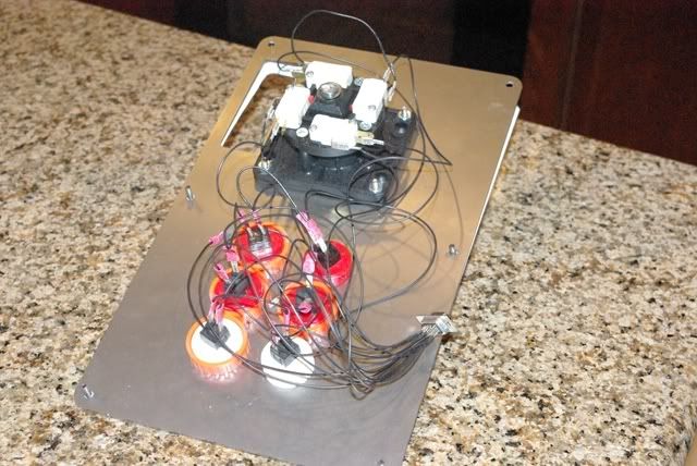
(My wiring is not neat but it works all the same, i just wanted to get this done fast for you guys to see so i did not focus on neat wiring. You want neat wiring go to J&J Socal modding and get them to do it.)
Now that it is all wired up you can place it inside your TE, not only that but you can now remove all of those colored wires
except the last two rows which are start and back.
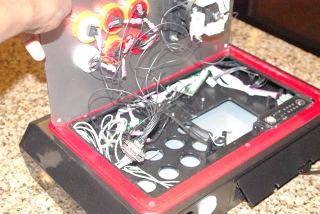
You can see the wires removed
With those wires removed you how have so much more room for your customized panels.
*Note that they do not have to be removed but i hate them so i removed them.
Now just connect your db 15 from the panel to the db 15 in the stick and Test.
Here is another pic
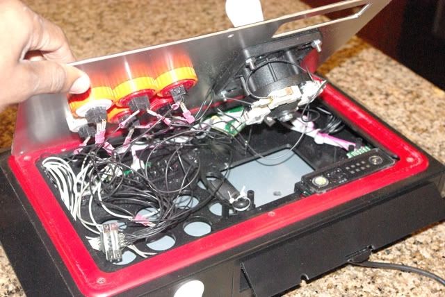
If testing works then congrats you have a easy removeable panel and can make more at will.
Also to let you guys know just in case you hate the idea of soldering those wires again for another panel. Well guess what, you dont have to.
If you really hate the idea of soldering more wires to more tiny db15s, you can easily remove the disconnects from the buttons and joystick and reuse the db15 on another panel. If it is a panel that does not need the joystick wires simply place some black tape over the disconnect. The same goes from going to 8 button to 6 button, just place tape over disconnects not being used.
One more tip is if you are using a joystick with the connector like the jlf or the ls 32 01 then you can simply connect the wire harness that came with the TE so you dont have to wire up the directions.

