After trolling this board as well as other technical boards for months I’ve managed to reproduce the results of toodles’ awesome imp switch on a breadboard. I have a background in electronics though I am in no way an expert or passionate about it. I have no intention of designing a PCB or manufacturing these myself but if anyone is interested in a way to switch pcbs without adding an external switch I’m more than happy to share what I’ve learned. It’s a fairly inexpensive process and only requires a couple of chips and a simple arduino program.
This is awesome.
I have a few old Imp or Imp2 boards lying around from older projects, but they were great.
I don’t believe Toodles is making any more (although he is making more MC Cthulhus sold via Paradise Arcade Shop), and I know Gummo had his version (called the GIMP), but he’s been relatively dormant on the modding scene (and spending time with his kid).
I’ve been toying with the idea of doing some PCB designs recently (mainly ideas to make my own modding life easier); if you could share your findings, it would be awesome.
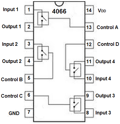
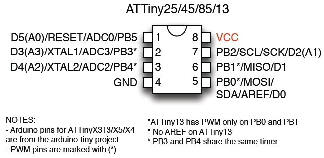
I used a quad bilateral IC4066 and an ATTINY25 microprcessor for this. Here are pinouts for both chips and a description of what I did with each pin.

Pin 1 = PCB1 D+
Pin 2 = USB Out D+ (tied to pin 9) This is also pin 6 on the rj45 connector going out of the case
Pin 3 = USB Out D- (tied to Pin 10) This is also pin 5 on the rj45 connector going out of the case
Pin 4 = PCB1 D-
Pin 5 = PCB1 D- Control (tied to pin 13)
Pin 6 = PCB2 D+ Control (tied to pin 12)
Pin 7 = Ground
Pin 8 = PCB2 D+
Pin 9 = USB Out D+ (tied to pin 2)
pin 10 = USB Out D- (tied to pin 3)
pin 11 = PCB2 D-
pin 12 = PCB2 D- Control (tied to pin 6)
pin 13 = PCB1 D+ Control (tied to pin 5)
Pin 14 = Voltage

Pin 1 = unused
Pin 2 = Button input (Home/Guide button)
Pin 3 = unused
Pin 4 = Ground
Pin 5 = unused
Pin 6 = PCB1 Control (tied to pins 13 and 5)
Pin 7 = PCB2 Control (tied to pins 12 and 6)
Pin 8 = Voltage
I used a “Sparkfun Tiny Programmer” to program the ATTINY
I found the chips and programmer on amazon fairly cheap.
This is the arduino code I used:
int cthulu = 1;
int ps360 = 2;
int guide = 3;
int val = digitalRead(guide);
void setup()
{
pinMode(cthulu, OUTPUT);
pinMode(ps360, OUTPUT);
pinMode(guide, INPUT);
}
void loop()
{
if (val == HIGH){
digitalWrite(cthulu, HIGH);
digitalWrite(ps360, LOW);
}
else if (val == LOW){
digitalWrite(cthulu, LOW);
digitalWrite(ps360, HIGH);
}
}
