seems like a lot of people are getting the Madcatz pads for DC hacking.
Have people confirmed which are version 2 of the pads? Is it only the clear orange and purple pads?
How about the clear one? I see these on ebay sold in sets of 2, a clear one and a clear purple one. I hope those are version 2.
Also, did someone find out where the 5v is and if it’s hard to wire without frying the controller port? I suppose I’d have to buy a multimeter to be sure, but since everyone seems to be buying a Madcatz pad, I figured it would save everyone a lot of time if someone could point it out. Either that, or I’ll build a webpage to show people once I figure it out myself.
Thanks guys. I’m rebuilding a busted Mas stick that my ex-roommate sabotaged. She actually unscrewed the back of the joystick and broke off random pieces from the inside haha. what a nut.
Hi all. I had made a new thread for this but it was suggested that I post my question here, so here goes.
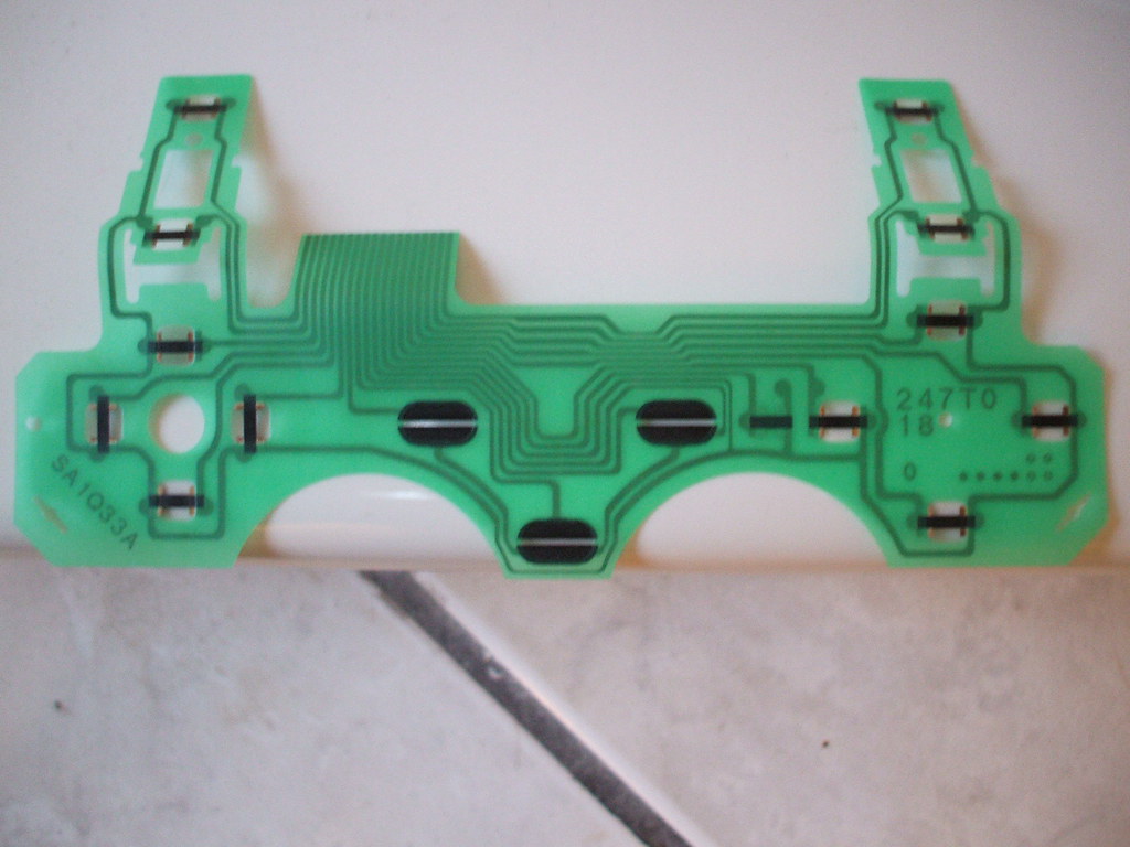
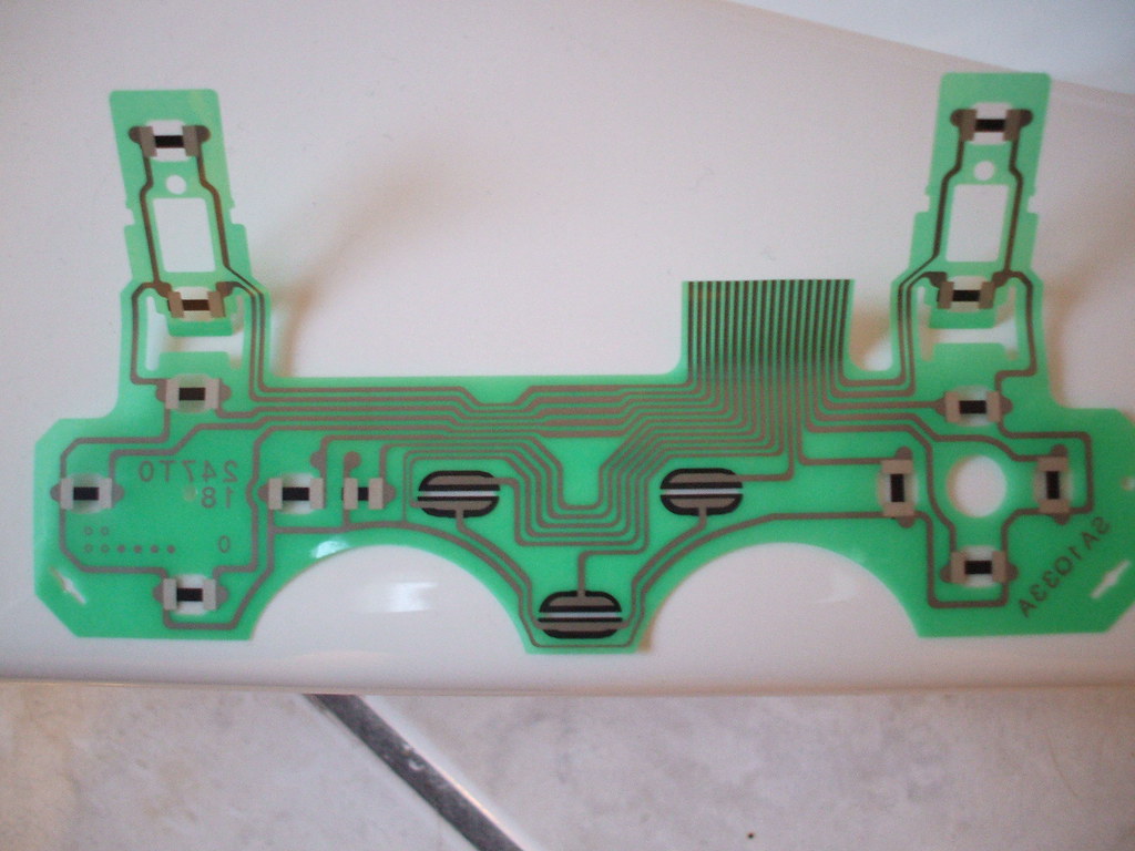
I’m attempting to use the SpiffyShoes solderless PCB hack but am having difficulty with this PS2 DualShock 2 “A” series board. I’ve determined the pin layout to be:
L2
L1
Up
Left
Down
Right
Select
Analog
Start
Ground (for 7, 8, 9)
Ground (for other buttons, directions)
?
Square
Cross
Circle
Triangle
R1
R2
By using the #10 ground, I am able to get Select and Start to work (and presumably Analog). However, I cannot seem to get any other buttons/directions to work. I have tried using 10, 11, and 12 as a ground but can’t seem to get them to register.
I’m not even sure what 12 really is and I’m sure that’s part of my problem.
Can anybody give me a hand with this? I’ve been through the packhacking thread but didn’t see any mention to the 18-pin DS2, only the 16-pin DS that SpiffyShoes used in his article.
That’s because DS2’s are hard, and every time to question comes up, and believe me, its come up a bunch, the answer is ‘Its hard’. Are you ready to solder over a dozen resistors onto the board?
Thanks Toodles. Guess I’ve have to scrap this project. I just figured there would be a way to have the other buttons operate in digital mode like the Start and Select buttons seem to be.
Ah, so, it’s about soldering a lot of resistors to the DS2 board. Thank you Dev for bringing it up again and to Toodles for finally expanding on the “it’s hard” answer. Now I can scrap my DS2 padhack projects as well without fear of there being just a small detail preventing it from working.
TMO seems serious about getting it working, so I’ll be working with him on taking some measurements of the PCB and figuring out the best way to do it. I had assumed that the pad would crap the bed if the resistance between the two halves of each button were 0 resistance and would mess up the analog reading of any other button, but I may be wrong on that. If it had been the case, then yes, one resistor for each button/direction plus a couple of others would be in order. Let me have him check a few things with a multimeter and we’ll post up what we find.
I just some multimeter measurements. If you’re comfortable taking resistance measurements and voltage measurements (the resistance measurements will be unplugged. The voltage measurements will need to be plugged in, preferably into a powered PS2), I can start listing off the things to measure.
I just cracked open the multimeter I bought myself for Christmas and I’m willing to give it a shot. Resistance measured without power. Voltage with. Check! =)
Need these resistances, with the ribbon IN.
-Resistance between pins 11 and 12
-Resistance between pin 11 and pin 1. Check to be sure that whatever resistance is the same as the resistance pin 11 and the rest of the buttons/directions. Looks like it should be.
-Look at the three points in the shaded area marked VR1. Ignore the middle one. Of the two outside points, one should be connected to pin 5 on the end of the PSX cable; that’s the pin in the very middle. The other should be connected to pin 4 on the end of the PSX cable; one of the pins next to the very middle. Once you have that, we’ll be using that point on VR1 to check some other things, like the voltages. I just want us to be sure so you have an easy point to connect to real ground.
Hi everyone,
I have a few mas sticks and a lot of dreamcast pads laying around the apartment.
my dilemma is that in one of the mas sticks i want to replace the pcb with a dreamcast pad pcb.
is this fairly simple to do? i am familiar with soldering and using a multimeter… but will this be difficult?
Sorry. I screwed up already. I saw that the ribbon was in but it was cut, since I was following the SpiffyShoes guide where he suggests removing the top portion.
I am remeasuring on a second controller and will update my other post with the proper measurements.
Thanks for redoing. I saw the original numbers and knew they couldn’t be right.
To check the connection between the points and the pins at the end of the cable, set the multimeter to the lowest resistance setting. Put one probe on the middle pin of the PSX cable. Touch the other end to each of the outer spots on VR1. One should show almost 0 resistance, and the other should show inifinite resistance (it may flash for a sec, and then soon increase to infinity). The one that shows almost 0 resistance is connected to the middle pin, which is VCC, and we’ll call that the VCC point from here out. The other VR1 pin should show almost 0 resistance to one of the pins on either side of middle PSX pin. That’ll be the true ground. Don’t skip checking the GND. We want to be sure it is connected to that pin #4 on the PSX cable.
DC soldering points are supposedly difficult because you have to solder to the contacts themselves, so the soldering points may break or come off. Madcatz dreampads on EBAY are cheap (like $7 with shipping) and have holes that make it much easier to solder to.
if you make a hole in the DC pad pcb, you may fry your controller port on your DC, so it’s not worht the risk.
one thing tho is that if you’re hooking up a p360, you may have to figure out where the 5v line is on the Madcatz Dreampad which nobody has replied to my previous question about.

 No, I’m not.