According to aznchristmas the microswitches become quieter and smoother with age and use:
Is he right? The sanwas 8YT I tried in the arcade had hardly any clicky and silky smooth whilst the 8Y I have is very clicky but brand new.
According to aznchristmas the microswitches become quieter and smoother with age and use:
Is he right? The sanwas 8YT I tried in the arcade had hardly any clicky and silky smooth whilst the 8Y I have is very clicky but brand new.
Hi Akuma, is there a guide out there that shows where to solder these resistors onto, say an official pad pcb? I have some 10k resistors somewhere. I want to experiment making a common ground pcb. Thx.
edit - n/m i’m too much of a noob to try this yet. 
8Y and 8YT are the same stick. The added “T” only indicates that a mounting plate is included and already attached.
Regarding the different feel of the one in the arcade, I can almost guarantee that it has been used a ton, and has been well worn-in (like a good pair of hiking boots); this has made the spring and switches loosen up a bit, which makes for a smoother feel and softer clicking. The arcade cabinet itself will also muffle the sound of clicks to some extent.
thx, I was worried the 8y had inferior louder microswitches or something.
soo…i got a quantum fighter pad to mod… does anyone have any suggestions or hack pics?
thanks!
also what is wrong with using it?
Neat.
I just ordered a pair of those whacky madcatz arcade sticks to turn my American sticks into PS2/X360 hybrids.
I’ve seen pictures of the PCBs, but none with solder points listed. Could someone who has used one take a picture of the guts?
Also, I don’t have a volt meter. If I have to buy one I will, but if someone already knows the voltage line and ground line on that particular PCB (and a PSone H series for that matter) I would really appreciate an image.
If not, I’ll figure it out and post it.
Got a question. I sold a 360 stick that used a hacked gamestop pad in it. It wasn’t common ground, so I did a +v and ground wire for each button.
The buyer is telling me that after a few minutes of use, the fierce punch starts coming out on its own, in particular when pushing left or right on the joystick, and with other button presses.
Can you think of a situation with the wiring/soldering that would cause that?
The only thing I can think of would be that one of the quick disconnects pulled off the button posts, and the “stiffness” of the wire is holding it in place against the post. Jiggling or shaking the joystick (like you do when you play) is jostling the QD against the other post of the FP button, causing it to trigger.
It seems odd for that to happen, but it’ s the only thing I can think of.
^^bad wiring it’s makign contact with other contact points
Doesn’t seem likely, as all the connections on the contacts were soldered, tested, and then hot glued down. The chances of those wires hitting other contact points is near 0.
On top of which, how could 1 loose wire cause multiple different buttons to trigger fierce punch?
hey guys.
ive got a psx m series controller (no analog)
http://i72.photobucket.com/albums/i169/erikstanton/0110082023.jpg
can i use the ones labeled Rx? Ry? and Lx? Ly? instead of on the ones below?
i think this would be easier, but i wanna make sure itll work.
I have a Naki wireless which I recently replaced all the buttons and joysticks with sanwa 30mm’s and jlf joystick. It worked perfect for 2 days and now for some reason the wireless won’t connect. I figure I might as well buy a dualshock controller and make it wired.
My question is, is it as simple as removing all soldered wires from the wireless PCB, and reattaching the wire and ground from each button, and the 4 wires and 1 ground from the joystick to the pcb like in the padhack guides in the first post. Can somebody explain what the +3.3volt thing means in the second dualshock diagram? What extra wiring do I need apart from the normal buttons and joystick wires and grounds?
Yeah, you should just be able to desolder and resolder the wires to the new PCB, although make sure you read the guide as to which dualshocks have usable PCBs.
The 3.3v, I’d guess, is for people who want to wire the pad to a P360 joystick (which needs its own power supply). You won’t need to worry about that.
nevermind i did it and it works.
Thanks crackbone. Sounds pretty easy to do. I got a A series SCPH 1200, which I hear in some places is the best one to use for PS2? Anyway, can I still use the same guide for the series H? The buttons seem to be in the same place anyway. And the really thin sheet I’m supposed to solder onto, do I scrap off the black stuff first? Also do I remove the analog sticks and the weights they have attached?
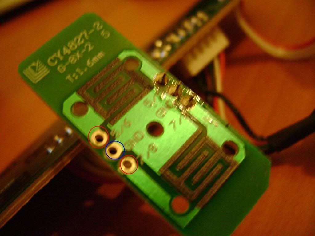
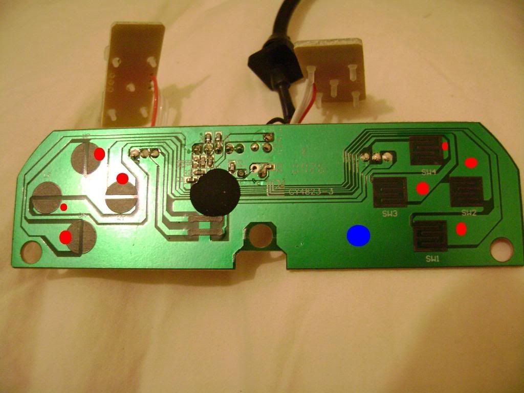
Can someone please help me finding the solder points on this PCB?
It’s a GENIUS MaxFire G-08XU, 8 buttons (4 at the face, 4 at the top)…
http://img230.imageshack.us/img230/3090/dsc01097at0.jpg
http://img152.imageshack.us/img152/7889/dsc01103dj8.jpg
http://img213.imageshack.us/img213/8975/dsc01092hr2.jpg
The pad I’m talking about.
Thanks in advance!! Great thread!!
This pad looks very easy. In the pictures any red spot is where you can scratch away lightly at the PCB to get to the copper trace for the given button. I am sure you can figure out what button is what by comparing the PCB with how it fits in the controller. And as for the shoulder buttons, the two side things circled in red are for the top buttons and the blue is the ground. Also the soldered areas across from the circled sections on the shoulder button can be used the same way. The controller looks like it has a common ground so you will only need one ground wire, just place it where ever you want.
http://i182.photobucket.com/albums/x277/Chaosdragon13/th_dsc01103dj8.jpg
http://i182.photobucket.com/albums/x277/Chaosdragon13/th_dsc01097at0.jpg
Wow! That was fast!
Thanks ChaosDragon13, just one more question: should I use only one ground (even for the top buttons?)
Again, thanks 
Is secure simply to cut the rumble wires of a dual shock? I don’t want the two motors inside the Stick.
Yes it’s safe to cut the wires to the motors
Your pad has a common ground for everything, so yeah, one ground even for the top buttons.