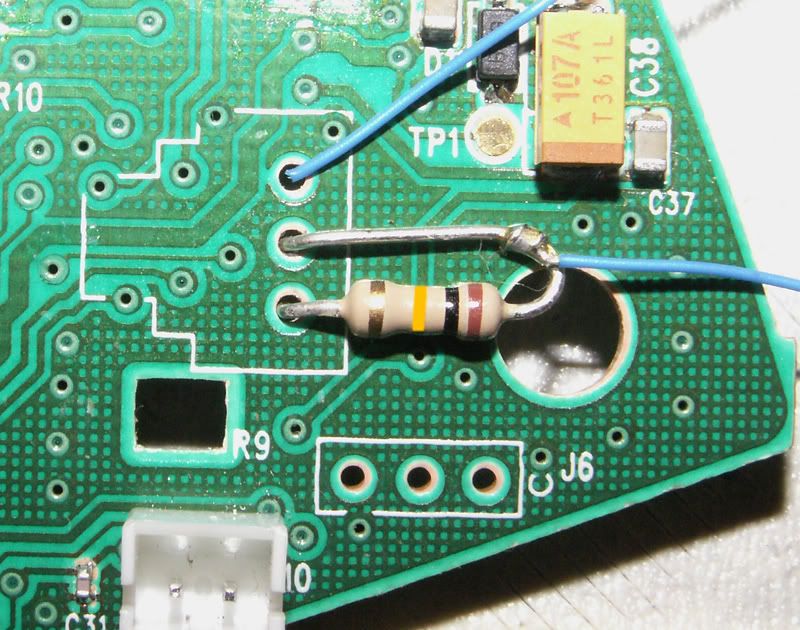
They are 4.7K 1/4 watt resistors. What I did with this pad is I followed the slagcoin pinout: http://www.slagcoin.com/joystick/pcb_diagrams/ps3_diagram2.jpg See how the resistors are soldered between the two points on the left and the common ground on the right. One set of buttons needs to be grounded to one resistor and other buttons to the other, PM me if you need more help. The controller will not function unless you put resistors in these places and ground to them, if you don’t, the only button that will work is the guide button.
It is easier to run the signal wires from the ribbon cable pins, but you should do all grounding from the resistors. I had to do it the hard way by soldering to the points on the board because I ripped out all the pads and traces when I was trying to pry up the top of the ribbon connector.
I have little round copper contacts right where the button symbols are on this image. Can I solder to those instead of the buttons themselves?
Also, does anyone have any tricks for soldering to those button contacts? I’ve had no issues with any other PCB but for some reason the PSX pad does not want to accept solder.
If you’re talking about those little dots that are in between the contact pad and the cable, then yes.
They don’t stick generally because you haven’t scraped that black shit off. you gotta scrape it pretty clean. i was having a tough time yesterday myself, it was usually because i didn’t scrape enough off.
Larger resolution please. A common ground would be one of the circuits that touches EVERY contact pad. Each button has 2 contact pads, the ones that touch the common ground, would be the ground, and the side individually goes to the cable, those are the signals. check out the diagram i drew a few posts above to understand what i mean.
If you click the image it takes you to the much MUCH larger shot of the PCB… I don’t plan on Dual modding this pcb though, so CG isn’t as important, but I would like to know which is the signal on the pad…
Anyone knows why slagcoin calls the point where sync button is connected “Wire/Wireless plug switch”? Is there a way related to that point to make a Wireless work as wired -P&C cable have active data lines, after all-?
Can’t be determined just from the picture, sadly. There’s a good chance it is common ground though. To determine which is the signal, use a multimeter. The top half of the three center buttons (minus, home, plus) is the ground; if the pad is common ground, then one half of every pad will be connected to those same ground pads.
Problem is, even if you get that down for the digital switches, your stick won’t have control of the analogs, so no control over the cursor in the Wii menu. Even if the digital pads are common ground, the analog part of the triggers are almost always reversed in a way requiring inversion.
I think you’ll find a PiiWee much much easier to use. You can make that pad work, at least in limited ways, but there will be some work involved. PiiWee would be a lot less work, and much more functionality than you’re going to be able to hack into that pad.
Thanks for your quick reply. Too bad it cannot be done, but I’m still quite sure this cable have ability to send data, as you need a driver to be able to charge it on a PC or it won’t charge.
Thanks Toodles… I already have 1 of your PiiWee’s and I’m ordering a 2nd (and prob a 3rd) at some point, but wanted to give pad hacking a shot since I had this controller lying around and didn’t want to crack open one of my 1st party ones… I’ll have a multi-meter shortly so i’ll go from there, but you gave me a great start
i have the chimp and i’m trying to find out where to connect the ground and the vcc to. the instructions say to put them where the black and red wires were for the usb cable but i detached the usb cable on the controller before i could see where they were on the board. can anybody help? i’m using a sf4 ken fightpad. thanks in advance!
Quick questions about analogs on 360 wireless early version: Should I use 4.7K for both connection buttons to triggers and neutering sticks? where exactly goes the cables on this picture : http://i50.photobucket.com/albums/f320/RDCXBG/SFAC%20Mod/LTWireless.jpg ? I’m assuming the one connected to the resistor to the button, but the other one?
