Well barring that:
On an early 360 wireless pad, if you’ve removed the triggers but don’t want to use them, do you need the resistors?
Is there an alternate LT1 contact? That shit just popped off.
Well barring that:
On an early 360 wireless pad, if you’ve removed the triggers but don’t want to use them, do you need the resistors?
Is there an alternate LT1 contact? That shit just popped off.
does anyone know any common ground ps2 wireless controllers to rip apart? :woot:
Unless you’re looking for something fancy, you can treat it like any other pad. If you haven’t removed the pots the easiest thing is probably to leave them in place (maybe glue them into position) - whether you’d need resistors if the pot is gone already is a controller-by-controller thing.
Some pics of 360 madcatz project
this is not the typical madcatz 4716 common ground controller, this was a 4715 without common ground. because of this i just ran ground and signal for each button.
you’ll see that i did a trigger hack with can be found:
http://forums.shoryuken.com/showthread.php?t=197388
i also use the RJ45 detachable cable idea, this is very cool. i just install a wall plate and have a very nice connector for my joysticks. also, it allows me to make any length RJ45 extensions for my cables, i just do a not so pretty splice. the tutorial can be found here:
http://www.shoryuken.com/showthread.php?t=178604
http://img526.imageshack.us/img526/3173/img0098g.jpg
http://img526.imageshack.us/img526/6812/img0025ra.jpg
http://img683.imageshack.us/img683/6093/img0107hq.jpg
http://img25.imageshack.us/img25/4370/img0106ba.jpg
http://img717.imageshack.us/img717/802/img0105jd.jpg
http://img696.imageshack.us/img696/5414/img0104j.jpg
http://img63.imageshack.us/img63/459/img0103f.jpg
http://img687.imageshack.us/img687/8585/img0102ik.jpg
http://img411.imageshack.us/img411/6612/img0101lt.jpg
http://img694.imageshack.us/img694/649/img0100b.jpg
http://img687.imageshack.us/img687/7808/img0099lk.jpg
http://img101.imageshack.us/img101/7826/img0097tp.jpg
http://img130.imageshack.us/img130/2661/img0096jv.jpg
http://img227.imageshack.us/img227/3638/img0095w.jpg
http://img51.imageshack.us/img51/8747/img0027ek.jpg
http://img263.imageshack.us/img263/2723/img0026c.jpg
http://img651.imageshack.us/img651/4382/img0024rrrx.jpg
http://img695.imageshack.us/img695/2994/img0023dn.jpg
http://img402.imageshack.us/img402/655/img0022ey.jpg
http://img541.imageshack.us/img541/4627/img0021o.jpg
http://img28.imageshack.us/img28/5379/img0020tr.jpg
http://img714.imageshack.us/img714/9923/img0019se.jpg
http://img405.imageshack.us/img405/9923/img0018ut.jpg
http://img534.imageshack.us/img534/4830/img0017j.jpg
http://img406.imageshack.us/img406/5245/img0016s.jpg
http://img18.imageshack.us/img18/8859/img0015sq.jpg
http://img263.imageshack.us/img263/5638/img0014xi.jpg
http://img101.imageshack.us/img101/7508/img0013no.jpg
http://img683.imageshack.us/img683/4590/img0012hv.jpg
http://img695.imageshack.us/img695/8713/img0011fv.jpg
http://img695.imageshack.us/img695/325/img0010gw.jpg
http://img685.imageshack.us/img685/1948/img0009ua.jpg
http://img51.imageshack.us/img51/5430/img0008mc.jpg
http://img519.imageshack.us/img519/8327/img0007hm.jpg
http://img341.imageshack.us/img341/3494/img0006vv.jpg
http://img532.imageshack.us/img532/4194/img0005fx.jpg
http://img696.imageshack.us/img696/5885/img0004kz.jpg
http://img130.imageshack.us/img130/498/img0003kc.jpg
http://img180.imageshack.us/img180/862/img0002ps.jpg
Yeah you can remove the motor wires using either one of these methods:
-Apply the soldering iron to each point where the wires are attached, then remove before solder hardens (preferred and recommended method)
-Literally rip out the the rumble motor w/wire (NOT RECOMMENDED, but still works)
I’m not too sure about removing the shoulder button boards (I left them on), but in case you mess up soldering to the copper circle points, you can instead solder to the metal points (directly below the copper circle points). Just be sure not to have any solder overlapping or interfering with the other metal points.
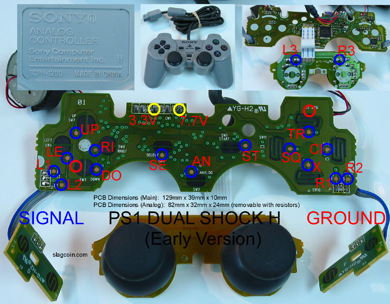
What is the purpose of those voltage spots? I don’t quite understand.
If i wanted to take apart a old Playstation pad of mine, and had some buttons and a joystick, don’t I just solder on buttons to the corresponding spots on the pcb? I saw diagrams and they all (if not all), have a voltage source labeled, but I never got why it was labeled for.
dual mods require them. Perfect 360’s require them. Led mods. Suzo Inductives and Sanwa Flashes. There are lots of reasons power is helpful.
I see. After looking at some funny and creative arcade cases, such as tupperware and shoeboxes… I may just do the same as well and rip the pcb out of an old PS controller I almost never touch, and this will play on my ps3 with an existing convertor I have. I wouldn’t need to worry about the power then, would I?
I was wondering what the ground (blue line) was for exactly in this diagram (was in OP)
http://arkadesticks.com/hackedpads/wiredPSOneand3.3volt.jpg
Correct me if I’m wrong, but why the blue wire is connected in this fashion is so that pressing a button will complete a circuit for that one button, correct?
There’s no real “left or right” side to the buttons, correct? The blue wire was hooked up to the left arbitrarily, meaning every other button should be wired on the left?
Anybody have an answer for this? Did I ruin it?
Common ground official 360 pad (old one).
Well, its been nearly a month, I don’t know if you’ve fixed it already. There are four points on the Dreamcast triggers which are soldered to the PCB. You should test them by grounding them to figure out which point is the correct one for the signal wire to your button. When you find it, use hot glue to keep it in place, the solder point is very small.
Although it sounds like your shorting if you get the problems with abx and y. I also have weirdness issues with my factory Dreamcast PCB, its just something you have to redo untill you figure out where the problem is.
So I’ve ripped open a generic PS1 pad of mine… How do I know which side of the d-pad directions I scrape? Same as the one shown in OP? Then what about the triggers? There’s no solder bits a the bottom corners as the triggers got their own boards. Every other question is in the image.
use a voltage meter, check for continuity between points to see if it’s common ground. if so, you can solder 1 ground wire to the pcb and daisy chain the buttons.
Electronics noob here…
http://www.chromesphere.com/coleco/coleco_Graphs/Joystick_Ground_Daisy_Chaining.jpg
this is daisy chaining?
Is a common ground where every button shares the same ground?
Which two sources am I checking for continuity? Put one end of the voltmeter on the left half of this button, and put the other on the right half?
You only need one part that says, “To Controller Board Ground.”
For your other Post:
Ground is the side with the super big green going everywhere.
For the Trigger, Ground is the Trace that you see L1 and L2 connect, and R1 and R2 connect.
And yes, that is how connect a Button.
How do you know that tall the big green section is ground just from this photo? I actually forgot to point out, on the back there’s a gray wire hooked up to a spot labeled GND, which I suppose is Ground. on the front it is connected to the big green slab on the left side. This would mean that this is common ground, correct?
edit: i think I’m starting to get this ground shit, let me work on a higher resolution diagram. This will help me fucking learn so I don’t have to ask so many questions. Thanks.
It just is.
That’s how I know.
You can scrape anywhere on the giant green stuff to solder wire for Ground.
Or any point you see is touching the big green stuff.
Or that wire you found.
Hey thanks a lot, jdm.
I got that diagram done.
This is how I’m seeing how this circuitry works as of now. is it correct?
Cool.
That is right.
How you make picture?
I really like the drawing of PCB and stuff.
You don’t have to use the scraped parts if you do not want to.
You can solder to the contacts opposite of the Signal.
Or you can solder to some of the purple dots (three).
what do you mean by soldering on the other side of the signal?
I threw those “contacts?” in there to illustrate whatall those lableled parts are, see that line of text. those points make up the controller’s cable, yet I have no idea what they all are an what they are for.
I drew everything from scratch on Photoshop, thnaks for the compliment, been using the basics of PS for 3 years.
This what I mean of course.
http://img203.imageshack.us/img203/7196/psxpoints.png
But scraping is cool too.