Why do you need the sync button anyway?
If you plug the play n charge kit into any xbox it will sync with it.
Why do you need the sync button anyway?
If you plug the play n charge kit into any xbox it will sync with it.
Really? I did not know that. That is very helpful information. I have always used disposable batteries in my controller. I just recently bought a cheap rechargable battery on ebay for this box. I guess I have’nt had much syncing expierience.
I searched up and down, so I apologize if this has already been covered (IF SO PLEASE DIRECT ME TO A GUIDE)…
I have a SFIV Mad Catz WIRELESS Fight Pad that I cannot stand using…I have a buncha extra sticks and buttons lying around and thought I’d build a stick from scratch…
I’m not *terribly concerned with lag, and the mad catz ps3 pad normally works fine…I see no noticeable lag and if there is it doesn’t matter to me anyway…
SO…I know that the pad CAN be hacked, but cannot find any tutorials or diagrams…I have schematics for the 360 version of the pad and can generally figure it out, but has ANYONE done a PS3 MC SFIV pad hack?
Can I get a witness?
Amen!
Get yourself a continuity tester or multimeter and you can figure out if it’s able to be hacked pretty easily.
^^ That thread is for the 360 pad, this guy is looking for info on the PS3 version.
First off, if i’m not in the right thread, please point me to the correct one, please. 
Anyway, I have a PS2 Nubytech Street Fighter 15th anniversary fight pad. Looking to mod it into a fight stick, then buy an adapter so I can use it on my PS3.
I’ve taken the controller apart, so now I have access to the PCB. So I’m looking to find out what the next step is to turning this into a fight stick. My biggest concern is that I’ve never soldered before, and I have no clue as to where to solder on this PCB. I have some pics below if anybody can help me out with this.

Again, not sure what the next step is, so any help with this would be greatly appreciated. This is my first time trying to build a stick from the ground up, so I want to make sure it’s done right.
First, you should get an old pad and practice soldering to the copper contacts (make sure you can do it without bridging two contact points, and make the wire secure if you give it a slight tug).
Once you’ve done that, here’s where to solder for the buttons (red line is your ground, just scrape that to expose copper and solder to that for your ground):
http://img28.imageshack.us/img28/4541/buttonscopy.th.jpg
For the directions it will be similar, you’ll have to remove that rubber pad though.
Alright, seems easy enough. Any good pics of what the finished product should look like? Not trying to be a idiot, but again, just want to get an idea of what I should be looking for.
This is from the madcatz pad hacking thread, but it’s a good start:
Alright, I appreciate all your help, man. Looks like I got my work cut out for me.
Last question, and I’ll leave you alone , lol. What type of wire should I buy for this?
.Cobra – you don’t have to scrape the ground trace – that huge glob of solder near the top end of LuckyDay’s picture at the end of his ground line will work just fine for grounding it. (And that shoulder button mini-pcb can be removed and that second solder glob is probably the signal pad for that shoulder.) Otherwise, LuckyDay’s diagram and suggestion is perfect, really.
Some 20-24 ga wire from Radio Shack should do you fine. (Lower number is bigger wire.) Stranded vs. solid and thick versus thin are both preference based. I personally like thin, solid wire but others will swear by thick, stranded. If you’re really strapped for cash you might be able to use the wire from inside a CAT5 cable; if you don’t have a (broken) spare any geeky friend or friend with a young cat or rabbit should. Dog owners might, too, but those are more likely to be slobbery.
Slagcoin has a good section on what wire to use and how to go about soldering. Other than that there are quite a few good soldering tutorials online.
^^^Yep
Read up on this page before you start for some info:
Thanks guys, much appreciated. Doesn’t look as hard as I thought it would be, tbh.
I was trying to figure out the best connection setup for extending a 360 PCB’s mic port to the outside world on a stick, and I’m wanting to clarify a few things by those who know.
I’m aware that the actual 360 headset jack is 2.5mm as opposed to the more common 3.5mm. The concern I have is the connections involved on this headset. If I’m to understand correctly, it’s ultimately 5 points of connection: ground, speaker+/speaker-, mic+/mic-. Is this correct? Or is it only 3? I’m perusing Mouser for a decent connector I can feed through my MAS case as the mounting location of the board itself is nowhere near any place that would remotely work. Ideally, I’d like something like this:

but I’d need to know the proper number of connections I’d need to be able to get full functionality available.
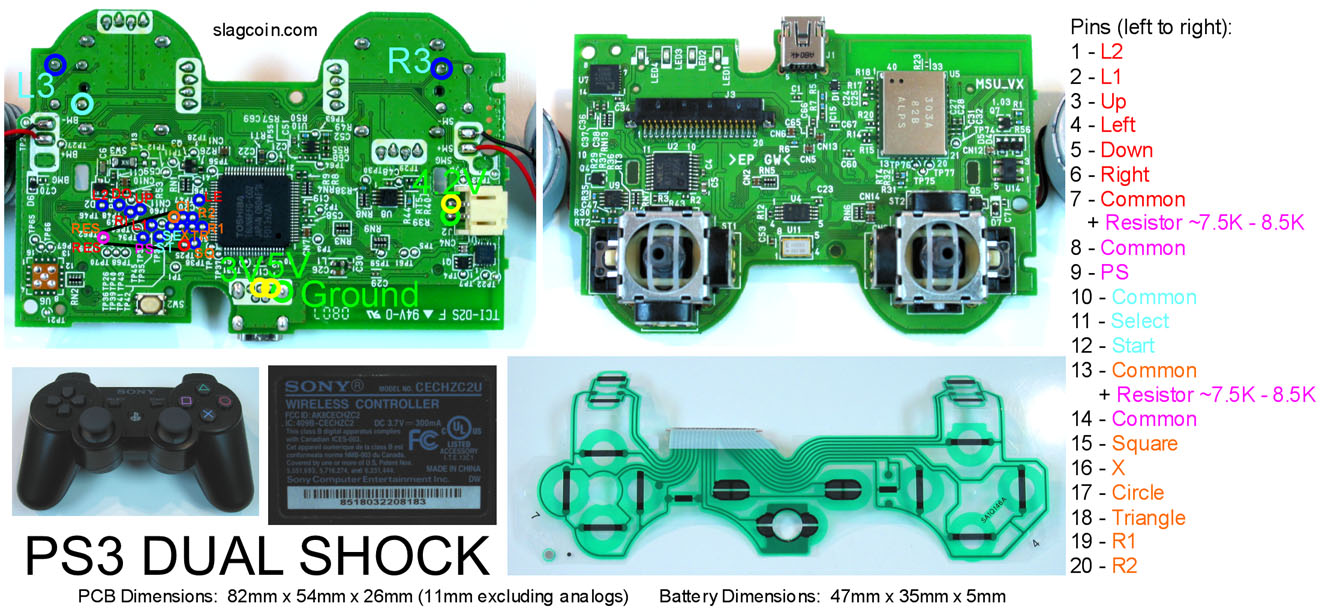
Hi everyone I was going to hack a PS3 dualshock 3 controller and when I opened it up I found this bad boy. :shake:
Does anyone know where pin# 1 and pin# 20 is or where does it start and ends? Thanks very much for your help.
in the upper left side, you see that group of 2x10 contact pads? Those are the pin #1 - 20. I don’t know off hand the numbering for it, but I have a few of those version of sixaxis boards. I can figure out the numbering later today when I get home if no one beats me to it.
hopefully if you scrape off the top of those contact pads there will be enough surface area to make a good solder joint. Otherwise, you’ll have to flip the board over and find the alternate contact spots.
Thank you very much Gummowned. So I tried to scrape off the black pads like you said but when I went to solder, the heat of the soldering iron is to hot, I figure, because the little exposed metal comes off.
Im using a 15watt soldering iron. Ive chipped two ps2 and a Wii with this iron and never had a temperature problem.I gess Ill have to go with the alternate solder points on this board. Theres no going back now sense I cant assemble it back together and use it. Heres the pic of the back of the board.
I was wondering how do I trace to the alternate solder points or, does someone know which are these alternate points? Im pretty sure their not but are they the same as this PS3 dualshock3?
Thank you very much for your replay:smile:
doubt slagcoin’s pinout will help much for the version you have. If you have a multimeter that has a continuity tester, you can find out the alt location. Might have a hard time finding the alt location for those last 2 that you burned off. I’ll post the pinout of the alt locations tonight.
I had to use an analog direction for my stick using an old (non CG, non CL) 360 pcb. All 3 other directions are soldered to d-pad points but left.
I figured it wouldn’t cause any problem at first but now I’m having doubts, when I guard low (down + left) and move back to standing guard (left only) its as though the game doesn’t register the left motion anymore. I’ve tried to repeat the ‘bug’ but it seems to only happen randomly.
Do you guys know if its a known problem when mixing analog/dpad together or am I merely screwing things up because of my low versus skills?
Ok so I solved my problem and soldered all the cables to my ps3 dual shock boar. The problem was that I was using a wire which was too big a gage and I did not scrape the black pads all that well.
For the damaged connections I found the alternate solder points on the back of the board.
Now does anyone know which is the first pin and which is the 20th