nobody is gonna answer me huh? ok
If you post a picture of the pcb, maybe someone can. Madcatz makes a lot of pads, we need specifics or no one will be able to help you.
Not to be nitpicky, but can you take a higher quality, higher res photo? I can’t see shit, cap’n.
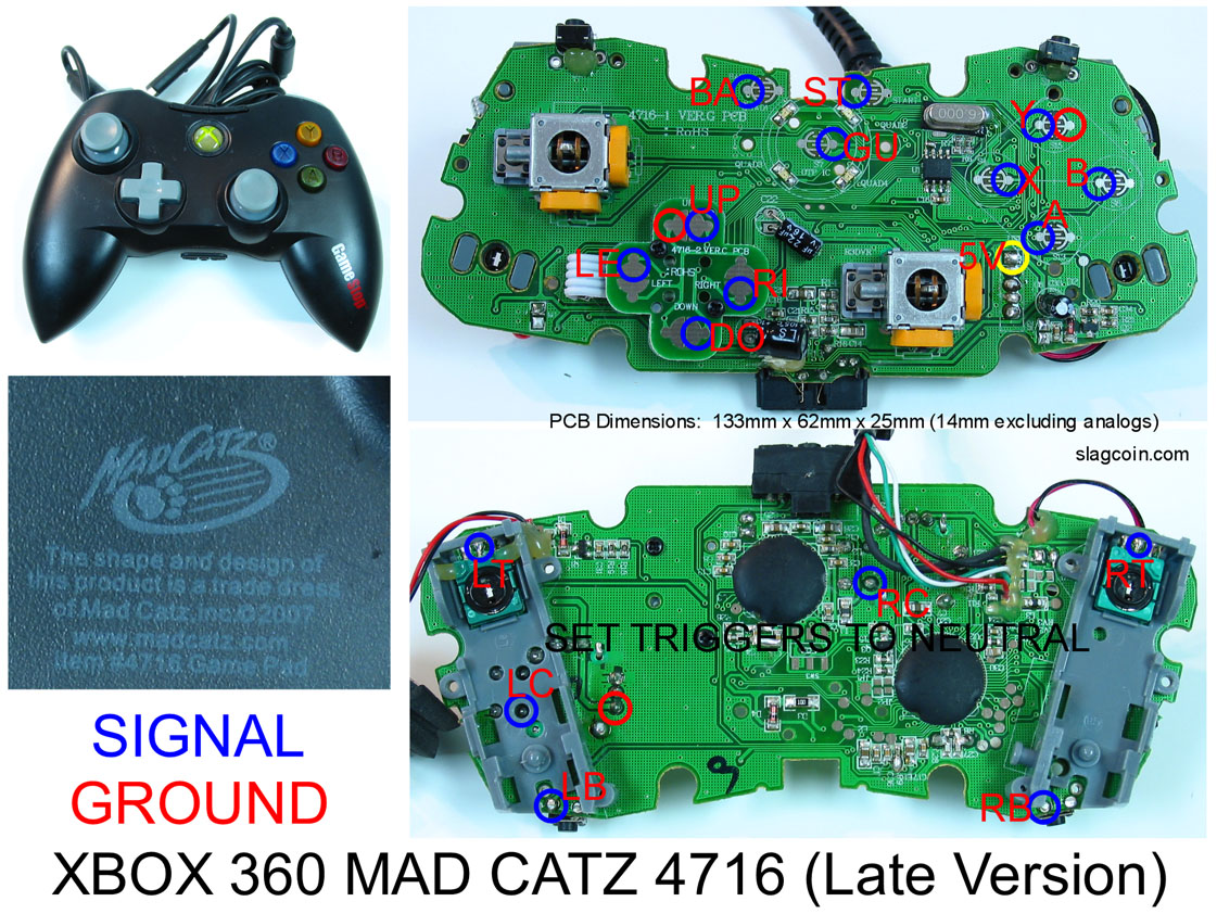
has anyone hacked the 2008 model of madcatz 360 wired controller. From what i understand it is common ground in a few places. For example the d-pad is supposedly all common ground, but when i soldered all of the signals from my sanwa jlf and soldered the 1 ground to the up ground all up worked, so then i soldered it to my right ground. The left and right worked then but no up and down. Where am i going wrong. I do not want to waste more time working on the rest of the PCB if i can’t get this right. Please any advice any one. I was using this diagram.

I know it’s a 2007 pcb but the item # 4716was the same so i was just guessing that they were the same. I am wrong? i really dont want to cut peices of my sanwa jlf’s pcb to get their individual grounds.
Hey guys I have the stick and buttons mounted on a Tekken 5 mod, but the stick wasn’t responding earlier, start button didn’t do anything? Am I missing something?
Also I have a JLF in there, so is it normal that I will have so many of the ground wires unused from the PCB, I only need one of them right?
Once I figure out this issue I think I’ll put together a tutorial for how to do the sanwa mod because the links on the himura-games website are all dead and the descriptions aren’t very good.
u can desolder the microswitches from the printed circuit board if you don’t wanna cut/damage anything.
Any one have a diagram for the Dreamcast Mad Catz Dreampad? I got one that is labeled “HB DC26-1 REV 2.1 12-99” Any help would be great thanks.
Does anyone know if I need to cut the traces for the grounds to put a JLF TP-8 series in a Tekken 5 stick since I think it’s not common ground? Or is there some way to ground it properly without cutting the traces, because right now I only have Up and Left directionals working. :sad:
until i am able to get some better pics up anybody know the basic general rules when tryin to solder a madcatz ps2 pad??? i really need help bad
I am hacking a MadCatz Wired 360 controller (late version) and having some problems.
Do you HAVE to put resistors on the analog triggers and sticks? Can you just ignore them and not use them?
I have seen people say you can just not wire the analog controller but I got my controller wired up and now the controller is not recognized at all. Not in a 360 or a PC.
You could also just buy four microswitches from Lizard Lizard or Happ’s. You can remove the original microswitch board and replace them with the switches. Grab some .187" QD’s and you’re set without have to do anything destructive at all, plus you wouldn’t have to desolder the microswitches just to solder to them again once they’re out.
Analog sticks? Nah, you don’t have to do anything kinky with resistors if you don’t want to. Just leave 'em alone and everything’ll be fine.
Triggers? Well, that depends on if you are planning on wiring the triggers to buttons. If you want to control the triggers with a button, you’ll have to get kinky and complicated with it. If you plan on just using LB and RB for your fierce and roundhouse, then you can leave the potentiometers on the board, turn them until the trigger isn’t showing as pressed, and then leave them there, maybe locking it in place with some hot glue.
Ok, thanks. I am just leaving them alone and not using them analog triggers.
I have wired quite a few PS1 controllers so this isn’t my first pad hack but it is my first with 360. I checked all my connected with a multimeter and they look good.
Any idea what could be causing the controller to not be recognized at all? Unfortunately I didn’t plug the controller in to test before I started working. I wonder if I got a bad used controller?
Hey guys. Search function not working right now…hoping someone can help me out.
I know it’s not the coveted madcatz controller but I just got this in black…has anyone had experience dealing with this pad? Common ground? Good stuff?
I wish I had read this, I just pulled off an analog potentiometer form the board and unfortunately it took the trace from the board with it… guess I didn’t desolder properly…
Anyway, Will this mean the trigger wont be engaged? I 've tested on pc and it’s recognized at -32767. When I turn the other trigger pot all the way counterclockwise, it registers as the same value. Is this off?
No where near enough information in ‘not to be recognized’ to help. Be more specific. Try it on a PC, use a multimeter to make sure its getting power, check with the light do, etc. Troubleshoot.
Good pictures of the board itself would be most helpful. Both sides.
If the pot is torn off and nothing done, the wiper pin will be floating; it could easily act erratic and activate whenever it feels like it; Follow the trace of the center wiper pin, and lock it high or low with a resistor.
Is that -32k on or off? I don’t know. Check in a 360 game or the dashboard which way you have to turn the pot to activate the trigger. Then, keep turning it that same direction all of the way until it stops. Use a multimeter to measure the voltage on the middle pin; if its high, then you know high voltage is ‘pressed’ and low voltage is ‘not pressed’ - so tie the middle pin to ground so its always not pressed. If the middle pin is low voltage then you know low voltage is ‘pressed’ and high voltage is ‘not pressed’ - so tie the middle pin to the high voltage pin so its always not pressed.
Thanks, it seems -32k is ON, as that’s the reading I get when I short any directional input.
looking at

this image, triggers are neutralized with the 1.5k resister soldered to the two outside pins on either side?
Then what’s going on with the 2 3.3k resisters connected to seemingly only one of the analog sticks. Are those resistors connected to each other and then to the pin in the middle?
Well, not neccessarily an indicator.
Yup. IF that is the exact pad you’re hacking, go for it.
Analogs stick can go up or down from a middle point. Triggers go from one end all of the way to the other. One resistor, and its tied to one end, either all the way pull or all of the way released. Two resistors ties it in the middle.
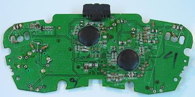
Okay I just cracked open a madcatz 360 wired controller (late version) and I think I may have borked the pcb. Anyone able to check the pics and tell me if I’m right? Checked slagcoins site and he’s got the triggers still on the pcb, well at least the casing around the triggers. I wasn’t planning on using those buttons anyways (LT and RT), but I was planning on using the right and left bumpers so let me know if I need to get another controller asap please (or if this can be fixed), thanks. Posted this in the noobie thread also hehe.
