I Purchased a Tatsunoko vs Capcom ( Wii ) Fight stick.
I want to replace the Printed Circuit board (PCB) with a Madcats 360 PCB.
This should work find right? any hidden problems that anyone knows about, ?
Besides soldering the wires to the correct places on the PCB, is there anything else to the process that I might not know about ? I believe its as simple as replacing the board and soldering wires into the correct places. I’ve watched tutorials on the subject. I believe the tatsunoko should be similar enough to the SF4 SE, that it should be the same, but I have not found any video tutorials specifically showing the Tatsu fight stick and specifically the madcats 360 controller.
I am just asking if there is anything unique about these two parts that I might not know about.
any unique things I may have to do to the 360 controller pcb or tatsu stick. besides soldering and mounting the pcb somewhere.
=====================
This is the inside of a SF4 (SE) Fightstick.
Should this match up match up with the insides of the Tatsunoko fight stick?
I guess I will be able to follow the differences if there are a few.
Ive seen alot of little tutorials about different parts of this operation.
Does anyone have a single tutorial that walks me through PCB replacement ?
Tatsunoko stick to madcats / 360 tutorials would be perfect.
Basically im just replacing the “Main PCB” in the stick with the controller PCB.
which means probably cutting off the connectors on each of the cables that connect to the “Main PCB” so I can solder those connections directly to the madcats-360 controller pcb.
On the 360 controller PCB, I only see 3 total ground connections, one near the ‘X Y B A’ and one near the ‘D-pad’ and one on the backside.
Can I run all 8 ground from the 8 pushbuttons to one ground, one ground from the stick to thed-pad of the controller pcb and the last ground button from the home / turbo button to the backside of the controller PCB? that will work fine right? the 8 pushbutton grounds being in one ground location wont interfere with each other and lock out button combinations correct?
what connects to the ‘5v’ yellow connection on the controller pcb ?
Nice, it looks like you did your research, you get points for that. Looks like you know the bulk of what you going to do.
There no formal guide but I can help with this. The how to mod your SFIV SE Fightstick FAQ
and the following answers to your questions
1.Besides soldering the wires to the correct places on the PCB, is there anything else to the process that I might not know about ?
Not really. I would solder a wire to each of the signals.You may or may not have to invert the triggers if you want to use RT and LT.
2.Can I run all 8 ground from the 8 pushbuttons to one ground
Yes, that is how we pros do it. As for ground, that mad catz pad the 4716 is common ground. meaning all the buttons as well as directions share the same ground line. You can make what we call a daisy chain. Alternatively you can have the Xbox PCB wire to that smaller board the buttons are all wired to. Once side is all the signals the other is common ground. Looking at the traces on the button board should make it obvious which side is ground.
the 8 pushbutton grounds being in one ground location wont interfere with each other and lock out button combinations correct?
That is correct. Pushing 1 button will not interfere with the others. The boards encoder is looking for the voltage change when a signal touches a ground as a button press. Only the signal sides need to be seprate.
what connects to the ‘5v’ yellow connection on the controller pcb ?
That 5v is the part of the board you can tap to get 5 volts for various mods and hacks. For example people use it for lights, optical joysticks (as they need the power) and Dual-Mods which you aren’t doing any of those, so I would not worry.
“Main PCB” so I can solder those connections directly to the madcats-360 controller pcb.
Thats how we do it. I would suggest getting a barrier strip, preferably a European style barrier strip, to connect wires soldered on the Xbox 360 pad to wires connecting to the rest of the arcade stick. Idea is if you mix up two wires, you can just unscrew the terminals and swap the wires instead of unsoldering and soldering. You probably will not need each and every line. Just a ground and signal line to each button and to the joystick.
6.mounting the pcb somewhere
I would use Zip ties and cable tie mounts. Easiest, cheapest way to mount that board and you look pro doing so.
7.any hidden problems that anyone knows about
You will lose turbo, not like you should use it any ways LOL.Soldering wires for Home would be the trickiest for you.
I like to suggest instead of a Madcatz 4716 pad, try to find from the trading outlet a Xbox 360 SE or TE main board (they are the same)
Then the mod would be a easy swap with no soldering.
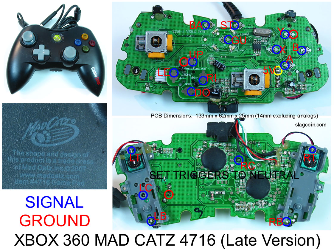
I found this picture on the internet, its the same model Madcats 360 PCB as I have.
It is slightly different than one I posted on the original post.
Notice the two little resistors connected to the red wires on the bottom corners of the board.
Is there a way around needing these resistors ? If I leave the base layer of the plastic casings from the trigger controls on the PCB (The little plastic housing that held the right and left triggers),
Normally the little plastic trigger housing holds that tiny wheel that turns when the trigger is pulled. will that work in place of the resistor? or do I have to remove the little plastic housing and go with the resistor instead? the original pictures from the tutorials shows the housings with the little wheel inside slid into the neutral posistion. like that little wheel will act find as a resistor. the the youtube videos Ive seen say to use a resistor. (Maybe because they accidently removed the wheel?).
I was asking because my gamestop 360 PCB is a slightly slightly newer model pcb than the ones from the old pictures. So I am not sure if the wheels work instead of resistors.
Would it just be easier to not use the trigger connects and use the buttons that you activate when you push the left or right stick in ? “RC” “LC” ?
I dont see where the “RC and LC” connections are on this specific 4716 PCB though.
these pathways on this PCB are similar but different than the PCB that I linked in the very first post.
the PCB I have is this PCB I linked in this reply here.
Madcatz 4716 triggers are engaged when they aren’t in use and those 3 points is where a potentiometer used to rest. The 3 points in the potentiometer, high, wiper and low indicate the position of the trigger. Normally buttons are engaged when the connection hits low, but for the trigger, it is engaged when it is on high. In other words, without that resistor network in place, it would be like your controller is pressing the triggers.
It looks like this is actually in use for an original Chimp board, rather than the SMD which does this automatically.
It also doesn’t look standalone unless the hex inverter which is needed to invert the signals isn’t in the photo.
RC and LC aren’t really necessary for fightsticks as those are the analog stick buttons when you depress your analog stick.
If you have a newer model Madcatz 4716 PCB, you must Invert the triggers, or use resistors/glue the triggers in place to neutralize them.
The older models required a 10KΩ resistor between High and Wiper, then solder the wire to Wiper, that’s why there is a resistor. However, this is a newer model pad. It was probably being used with ChImp or DualStrike using the inversion on there. However, you can use an Inverter chip to hack without Dual Modding.
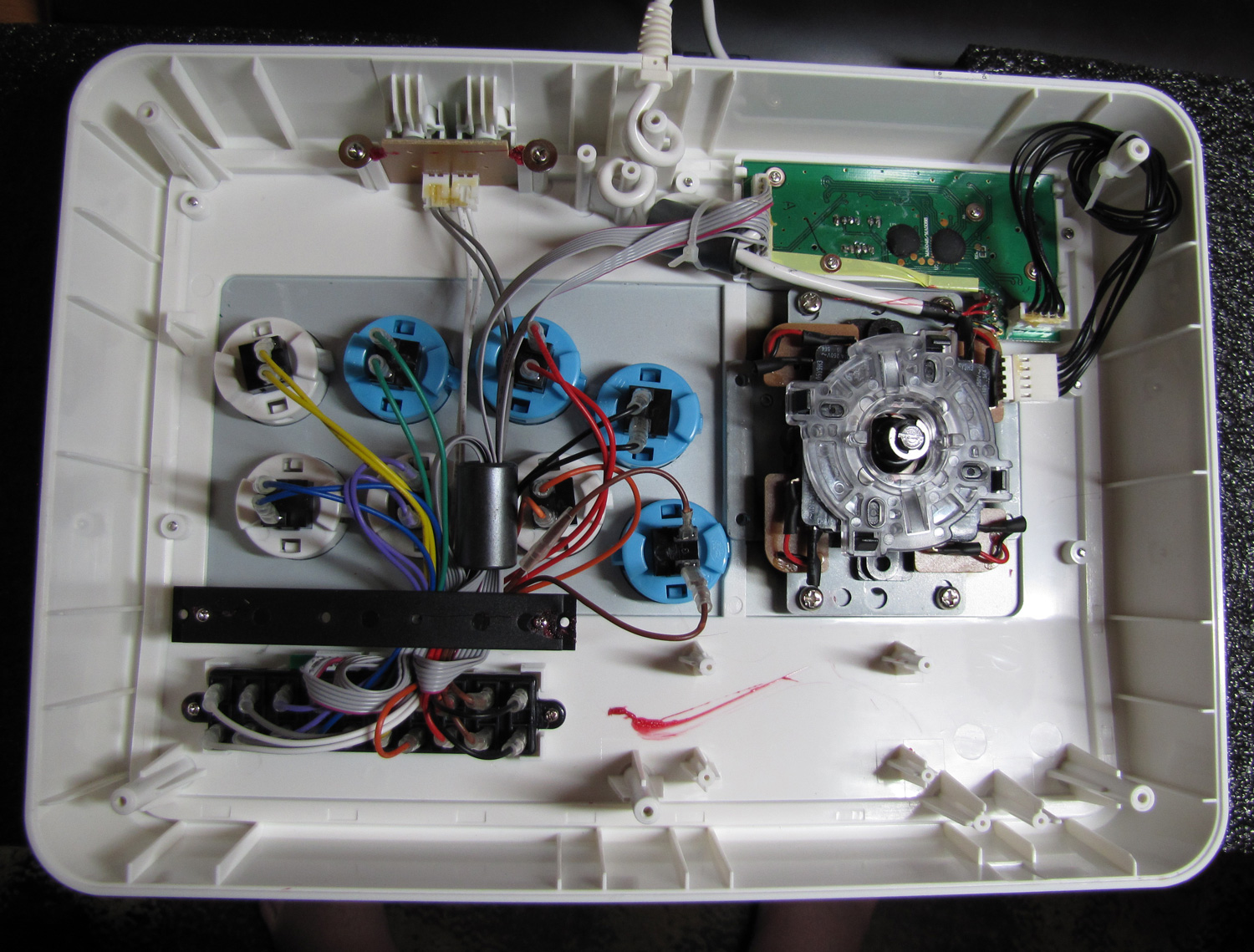
This is the inside of a Tatsu stick that I am using.
Since I have to replace the control panel PCB instead of a “main pcb” how do I retain the functions of the home button thats built into the PCB?
I can live without it if its too complicated.
Im trying to find wire diagrams for the tatsu stick. searching Shoryuken with three letter words like “PCB and TCV” doesnt work X_x. I have to google
"TCV PCB Shoryuken" and half the old shoryuken links dont work X_x.
Would it just be easier to wire the 3 Punches and 3 kicks button to the “RC and LC” Right and left stick push in button feature instead of inverting triggers?
If someone knows where those connections are on this specific cats PCB. I imagine that would be much wiser?
its not complicated to retain the home function on the pcb
you just have to link up the vcc from the tvc pcb to the madcatz pcb and the ground as well
you would have had to do that anyways to access the joystick directions properly
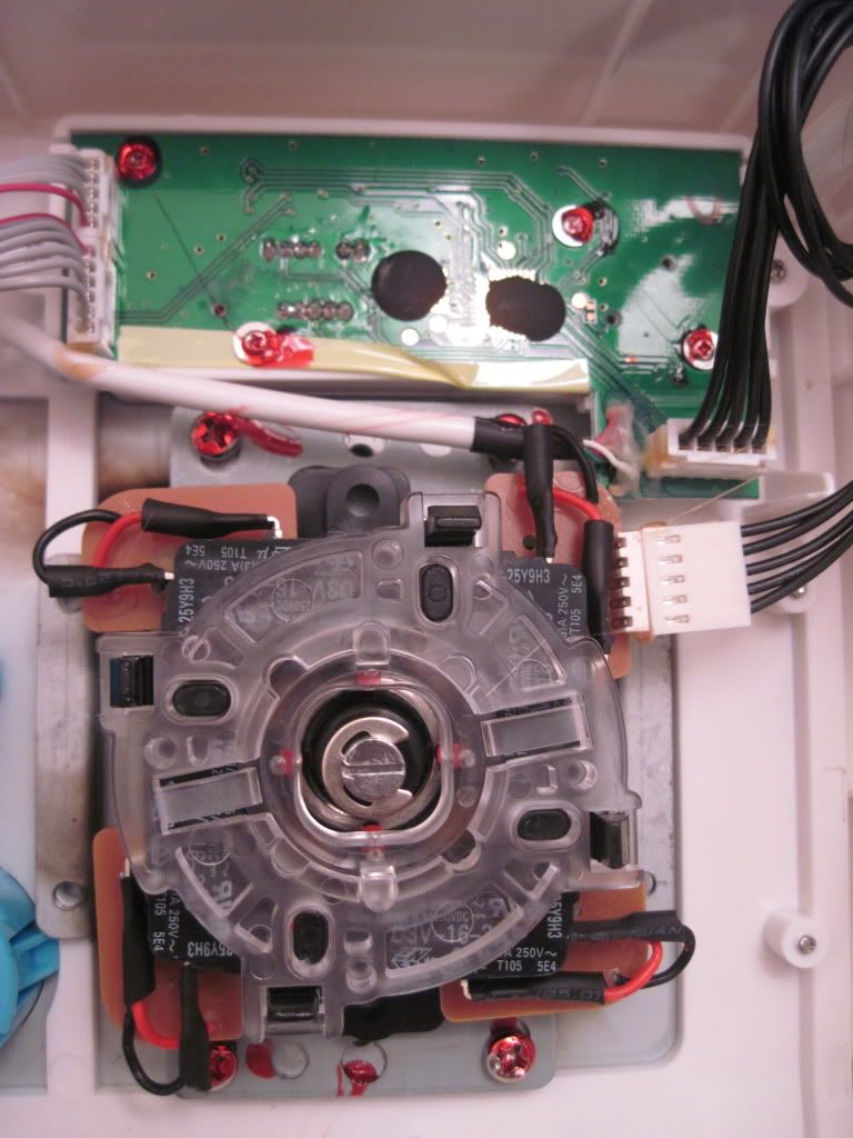
to access the home button signal, take your trusty multimeter and see the back of that pcb and how there are these nice giant easy to solder to circles. Use your multimeter and figure out which one of those is home (i’ll double check which dot it is in the morning once i wake up). Solder your home signal to that
I’ll receive the same stick but I has an old 360 TE pcb. I wonder if I just plug every wire on it, will it work (without the wires for turbo/guide as it’s not the same pcb) ?
If you have the Turbo Panel from the 360 TE, or a 360 SE, you could use that to retain the function.
You’ll need to solder on a USB cable if you don’t have one, but other than that, everything on TvC besides PCB in turbo panel is same as SE, which has same PCB as TE, so should work just fine. Shell is even the same as SE, if you had the screws that came with the PCB, you could screw it in place. Harnesses and barrier strip are same, too. So, you can just unplug from the Wii TvC Turbo panel and plug into TE PCB. Same with joystick.
You will, however, have some unused slots, such as the harness for the mic, plus the turbo panel harnesses. Do you need those for it to work, though? No, you just won’t have use of the turbo panel.
I tried recently, but unless I did it wrong, the nice spots in the back of the pcb aren’t the same like the ps3/360 ones… so you’ll have to solder to the contact points directly.