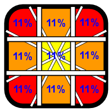
The reason i’m asking is because the diagram suggests that every diagonal has exactly the same proportion of cardinal directions, so i invite you guys to make a test. PS: [I gonna use de “right” direction as example but it’s the same for anyone of course].
Just press “right” from neutral and pay attention in the click and you’ll notice a little extra room till you reach the restrictor (i know, it’s the throw).
Now you gonna do the same thing but not from neutral in order to feel the difference, just press down, keep it and press the same switch that orresponds to the right and you’ll notice that is no extra room anymore, once you get the click you are on the restrictor already. (at least my not modded JLF is like this).
I believe this happends cause the actuator hit the switch sooner by coming from the middle and it gets the edge of the switch by doing the other way. As we know the switch along with actuator is rounded shape so if the actuator gets its edges means the switch is pressed later in comparison when it’s pressed in the middle.
My understanding about the diagram is that the switches should have the same throw after the click, no matter if the actuator hits them from neutral or not.
So Levered switches (Seimitsu) does match the diagram better, right?
As much as I value slagcoin.com, those diagrams are terrible for a few reasons. While they do illustrate the point that you get more throw into diagonals with a square gate vs a circle or octagon, the assumptions about the neutral zone and engage points don’t reflect reality, or even a consistent assumption about the neutral zone (which according to the diagrams changes based on restrictor gate profile).
That diagram shows nothing except more throws.
Look on focusattack for the image of the Kowal actuator. That image actually shows you what is going on.
There’s a point where the switch is ‘contacted’ but not actuated, and the switch is pressed and remains pressed even when you start moving the stick back towards neutral (when moving the stick back, the contact point is where the switch release occurs. This is actually a function of the internal switch itself.
The Slag Coins chart is just a generalization for Square gates and the range of movement.
You can’t quantify all square gates based on the designs of the Sanwa JLF. Even the Hayabusa acts differently enough to change up how the various parts interact.
And it is why the terrible kowal actuator gets caught in the Hayabusa and sometimes even the Sanwa’s JLF’s gate.
Neutral zones and engage point changes with each model of stick, and is effected by various mods.
The diagrams on the Kowal actuator on Focus Attack is misleading as well.
"Beware of actuators that decrease the neutral zone by simply making the entire actuator larger."
That line is bull shit as that exactly what the Kowal actuator works, same thing with the Paradise Arcade Shop (PAS) actuator.
The only difference is the PAS actuator retains the same basic shape of the stock actuator so the actuator engages the switches with the same direction of force that being applied.
You have to take in account not just the gate’s shape, but it’s design and construction, the throw and engage of the joystick, the length of the shaft, the size and shape of the actuator.
The kinds of switches used, the engage for the actual switch, if switch levers was use and if they are long or short levers, ect.
Like when modding a JLF for silent switches, a larger actuator has to be used as the silent reed switch omron microswitches plunger does not stick out as far (Edit) needs to be pressed in further, throwing off the engage from the stock joystick.
Also On Tech Talk we aren’t supposed to have VS threads.
Despite “vs” being in the title, his question isn’t remotely a real “vs” question. And all I said was that the slagcoin diagram is only useful for demonstrating increased throw into diagonals vs circle or octagon. Engage points will vary according to the lever design and whatever changes the user makes to it.
This is actually not true though, not at least with my D2RV-G-SD2s. The yellow plunger sticks out the same as that standard red JLF if not just a tad bit farther. The engage on the silent switch is longer than the standard.
Ed. As in here, it’s tough to get them absolutely lined up for my crappy camera, but the difference is marginal.
The pins don’t actually stick out any more or less. The activation point is just a tad deeper on the silent switches. Hence the bigger actuator to maintain stock JLF-ish actuation.
This thread could go somewhere if we weren’t all arguing about stupid diagrams.
This is easy to solve. Measure the gates. Measure the actuators, top and bottom. top is neutral throw, bottom is neutral engage. measure the switches as they’re mounted and the length of the pins. the distance between the pins and the neutral engage is the total engage, and then the neutral engage to activation is point of activation, probably 1.x mm from engage point.
With math and measurements this is very easy to solve, but is simply time consuming. It would need to be done for each model lever to really figure out the differences.
A side note, actuators shaped like the JLF hit the plunger on the face, compared to straight actuators like in the jlw or seimitsu sticks that hit at a point instead. Margin would probably be ± .x mm, so would still be accurate enough for illustrative purposes. This is simply for making diagrams. There are other factors as well such as mounting height, shaft length, but all we really want is an illustration for neutral, diagonal, and so on.