my first run TE pcb is no more, and i bought a couple $30 brawlsticks on amazon for backups for just such an occasion. im trying to just replace the pcb’s but the brawlstick has extra terminals on a few of the inputs. there are extra kgrounds and a p00. im not sure where they are supposed to go. it looks like the brawlstick is not a common ground pcb?
I took the main board out of the stick, hooked it up to the pc via usb and its recognized. I plan to just drop that into my TE stick and be on my merry way, except i have no idea where the extra terminals are supposed to go. Do they need to be soldered somewhere? in my research i read somewhere on here that the brawlstick wont work correctly without the “home button” pcb attatched as well, so i might just have to do a whole pcb innards replacement.
so what i see is,
the main button terminals both have a ground in the brawlstick (1 kgnd and 1 gnd) where the old te pcb just has 1 gnd. and the connectors on the right side of the pcb (looking at the front), both have 2 extra terminals although they are not labeled very well for me. so on the back, those 2 extra terminals are labeled “cn5” and “P00” for the top column and “kgnd” and “CA7” for the bottom column.
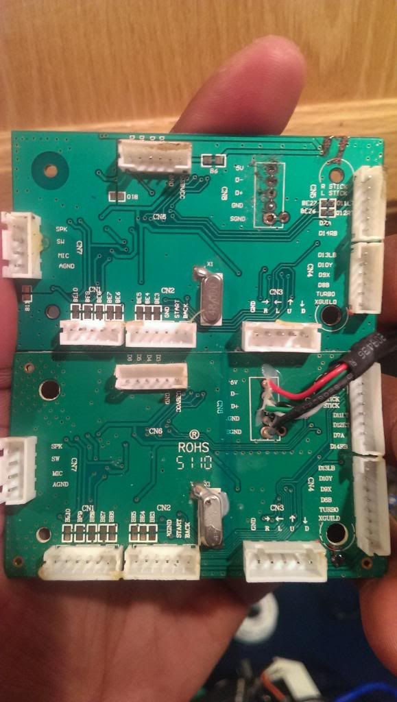
would anyone be able to point me in the right direction of what to do with these extra terminals? Im assuming that for the grounds and kgrounds, i can use the same ground terminal for each one? but what of P00 and the other CA7?
any help greatly appreciated.
I do not know what the extra terminals do exactly, but the main boards do get revamped every so often.
And I can tell you know, the guide PCBs can’t be exchanged between those two. Meaning if you want to use the guide PCB you have to match the guide PCBs with their main PCBs.
Well there a way to make the guide PCBs work but its too complicated for me.
word. i think ill do a complete pcb replacement then. might be the easiest route for me
Keep in mind I could be wrong, double check online.
Use google to search SRK to see if related threads pop up.
i was googling all last night. wanted to exhaust my search before specifically asking about it. i couldnt find anything describing or detailing the brawlstick pcb or any differences between that and the TE pcb. im going to keep searching while im here at work, but if i dont find anything, im just going to replace it all. its all good. just didnt want to have to crack open the other brawlstick if i didn’t have to.
The Brawlstick pcb is unique amongst the MadCatz boards released so far much like it’s Brawlpad counterpart. Yes it is common ground, but if you want to drop the motherboard in a TE stick then take my advice and swap out everything - the terminal strip, motherboard, turbo panel pcb, and all ribbon cables. You may have some trouble swapping the turbo panel pcb as it isn’t a perfect fit, but it’s nothing a Dremel can’t fix.
By the way, are you certain your original TE board is dead?
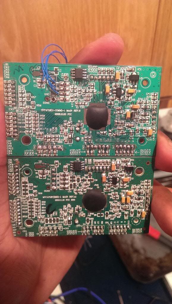
a while ago i tried my first mod, got a lot better since then, but i burned out the terminals i guess because its not recognized and wont boot no matter what i do. i kept it though just in case i ever wanted to try again, so i pulled it out again. when trying to repair the mod, i was told i could solder to the points where the blue wires are in the picture and tried again since my connecters were burned. i didn’t know an alternate to the 5v so i guessed that i could attach the wire to the jumper to the left of the 5v terminal.
i tried hooking it up a usb wire direct to the board and pluging it into a pc and got nothing. im going to keep it and still try to breath life into it, but i want to also play SF so i will use one i know works for now! that board is/has been a great learning experience tho.
thank you for your insight on the brawlstick
edit for grammar.
I’d say there’s a decent shot at getting your original TE pcb working again. Instead of those blue wires try soldering a fresh USB cable directly to those points and in the correct order. Copy the wire colour order from the Brawlstick pcb you’ve already taken out.
The alternative spots you have soldered to… IIRC for VCC / 5v you can solder the red wire to the large copper contact spot that looks like a tennis racquet (just underneath U2). I don’t have a spare 360 TE pcb on me at the moment so it is very important to check the traces for yourself. You may have already soldered 5v in the correct place - if someone else can’t confirm this by Friday night then I can.
word i will definitely try that
Please read my edit above - remember that as a modder a multimeter is one of your best friends.
just wanted to check back in with my progress. I ended up replacing out all the parts for the brawlstick pcbs. it was reletively painless just took forever with soldering and everything. I tried for about 2 hours to get my old TE pcb to come back to life and it just wasnt doing it, so i went ahead and put it back in the box for another day. if anyone else might want it I can mail it, or ill just keep it for another try in a few months.
thanx for all your insights.