PS3 dualshock 3 pin layout

Ok so I have this PS3 pad hacked and ready to go for my stick the only question is that I dont know which is the first pin and which is the 20th. Does anyone know where it begins and ends? Is the first pin the top right, top bottom, top left or bottom left? Any help would be greatly appreciated

I mean is the layout something like the black or yellow numbers? Or the other way around?

Here’s the layout from slagcoin’s site. Looks like the black #'s on ur drawing.

The layout for this pad is a bit different, to the OP you may want to try dropping this in the padhacking thread to see if any the guys there would be able to help you out a bit more.

-I have one of these pads as well lying around and would be interested to know as well so it doesn’t go to waste lol

I finished testing the board, and the pin numbering is like they way you have it in the black text. Even on top and odd on bottom. The pinout is the same as found on Slagcoin’s. I can’t tell you what the alt locations are for your board though, because theres at least 3 different versions of that type of board. The two I have have different looking alt locations. Funny though that they both of the pin number printed (unlike yours) and one of them have that black stuff (like yours) while the other one just has the copper pad already exposed.

i’m curious about this. :slight_smile: 
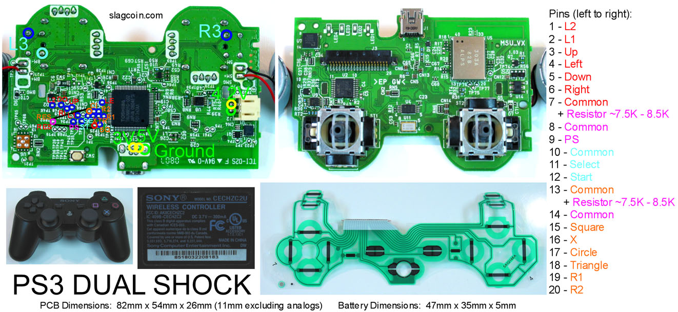
I was looking for a solderless pad hack for the ps3 dual shock and this is what i found.

now to my stupid question… how do you split the ground with just 1 wire :stuck_out_tongue:

Daisy-chain your Commons for the Joystick and Buttons.
http://slagcoin.com/joystick/pcb_wiring.html#SPLICING_AND_CHAINING

Daisy-chain.

Be careful what you are Daisy-chain.
Because you will NOT be doing Daisy-chain to Ground.

You will be Daisy-chain the respective Commons.
There will be three of four Commons you Daisy-chain.

Daisy-chain the red in diagram.
Daisy-chain the blue in diagram.
Daisy-chain the orange in diagram.

@jdm714 you’re always a big help!!! Thank you!

just wanted to make sure if i understand the distribution of the grounds before i open a dual shock 3.

feedback please

is the resistor really required for the whole thing to work?

can i use the the wires connected to the rumbles (the dual shocks) for an LED replacement?

No.
It is Common, not Ground.

Yes.

Yes.

sorry for the term :stuck_out_tongue: common i mean. but are the distributions correct on the colors that i made?

now i’m confused because of the resistors :frowning:

Yes.

thank you :slight_smile:
last. can this be done without going through terminals? i know it’ll be messy but i just want to know.

thanks for explaining why the resistors are needed as well

Yes.

how was the black part on the pcb removed? was it just ripped off or was it soldered off? here’s what i’m pointing at:

It came like that.
Both come as how you see.
There is more than one style.

i think mine’s the second one the one that has a black part. so is there anyway to solder through that or do i need to find an old dual shock 3 just like what he has?

What you have is the old one.

i see. but is it possible to just solder the wires directly to the pins? or can it be taken off and i’ll see the same picture?