Been having trouble dual modding my HRAP3 with a wired xbox 360 controller. Ive looked at many guides and wiring arrangements but i did not get much success. Most of my confusion also stems from wiring to the imp v2.1 board. Im following the instructions say on the PDF such as wiring the xbox red ucb wire to IMP “V”. PS3 USB wire to … such and such. Ive also tried rewiring the PS3 wires to the USB slots along the other side, but the same problem still comes up. When i test the wires by plugging them into my ps3 all the button presses register more than one button. Jab button would register jab, fierce, forward, and sometimes start. The only one that does the press correctly is the strong button, as the signal wire from the 360 PCB fell off the solder so it is the only button that does not have a signal to the 360 PCB. Also with the imp in effect with the PS3 is the 360 PCB supposed to light up the green ring on button presses cause it does that too. Any help will be appreciated.
Also note, that the directional buttons and the start, select, and guide button are wired backwards since black is supposed to be ground and red is the signal wire. Some of those might be backwards. but i soldered the correct ( or i hope) signal wire to the ps3 PCB.
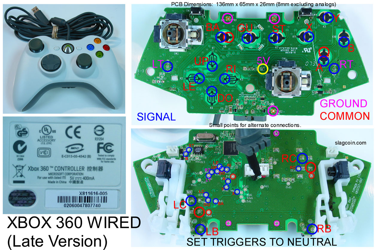
JDM is correct, that 360 pad isn’t going to work because it isn’t common ground.
You can’t have the Imp’s output USB also have the ps3 board’s USB wires connected at the same time. In effect, there’s no way to make the PS3 board shut up and not talk over the USB wires.
If you remove the analog sticks from a pad, you MUST tied down the analog signals with resistors.
Some soldering practice would be helpful.
There are professional modders available to do this work for you; unless you’re willing to write off the stick entirely as a cost of learning, you should consider hiring one to do the mod for you.
Thanks for the advice/ helpful criticism. Yeah this is my first time actually doing much soldering at once and dual modding. I have always been hesitant to do it, and did not have much time to allocate to it until now. I wanted to try to do it myself for experience. So, i would still need to keep in the analog sticks even if they will not be used to directly wire the signals from there? i actually wired the PS3 boards USB separate times when putting the USB to the IMPS output. I didnt have them on at the same time. But other than that, the wiring for the imp board is correct? Lastly, would i need to wire one of the common ground to a part of the PS3 PCB? Thanks for the replies/help very much appreciated
They are saying that you cannot use this 360 pad pcb at all, dude. The image from SlagCoin is deceptive as it is not a common ground pcb but it does share some common lines.
Please look for a different 360 pcb. I’d recommend either a MadCatz Fightpad or Brawlpad.
Oh - I’ve just noticed that the USB into the IMP could be another problem. Instead of having the black GND wire you have used the sheath mesh insulation.
My #2 may have been in error. It looks now like you’re using the USB cable from the pad as the outgoing USB, and cut the original USB wire to connect to the Imp’s D and E points, which is fine.
I would like to add that it may be difficult or impossible for you to put the plastic piece back over the PS3 pcb because of how and where you soldered the wires.
You do not HAVE to keep the analog sticks. You can remove them, but because they’re gone, the pcb gets confused and either thinks the analogs are waving frantically all over the place, or think it’s shoved as far as it can go into a corner, both of which are bad. There are instructions for tying down the signals with resistors on slagcoin.com.
I can’t swear that the wiring on the Imp is correct because I can’t follow all of the wires, but it looks like you’re using the green and black for D+ and D-, and red for power, in which case you’re looking good.
Oh crap, good eye Gahrling. Yes, black wire is better than the shielding with. the '‘thin black wire’ is the one you should use.
i see thanks for the replies. I already went out and bought the one that you mentioned above, lol so working with that for now. will see if i can get a hex inverter somewhere. sorry for being unclear earlier, but with the gamestop controller would i need to send one ground wire over to the ps3 hrap3 pcb? or would that be unnecessary?
Rules of a Dual Mod:
Both PCB must be Common Ground.
Both PCB must have the Ground be connected.
Both PCB must be powered at same time (VCC connected).
Well good news and bad news when plugged into the PS3 the board works. for the imp board i am using the guild lines to make start and select the home/guide button since the soldering i did on the home button might not fit the actual button. Works fine in the PS3 part, and pressing start and select brings up the home function. When plugging it into the 360 and pressing the start select nothing happens.
Did you short SJA and SJC?
Did you wire HRAP Home to Imp B?
Did you wire Xbox 360 Guide to Imp B?
Did you wire HRAP Start to Imp C?
Did you wire Xbox 360 Start to Imp C?
Did you wire HRAP Select to Imp F?
Did you wire Xbox 360 Back to Imp F?
yes to the first question, and as for the rest since they basically are supposed to have two wires from each PCB to the IMP. What i did was i wired the Xbox pcb start to the hrap3’s start and then had another wire from that bridge that went to the imp C etc for the others as well. Or should i do it separately from each PCB into the IMP board?
I thought you said that pressing Back + Start does not bring up Guide.
Meaning that your Dual Mod is able to switch to Xbox 360.
But the Back + Start = Guide does not work.
What really is your situation?
And updated pictures with the #4716 seen.
nvm i reread back on previous post and examined the situation. Turns out i was using the USB that was connected to the HRAP3 PCB board and thus why it only works on the PS3 part and not converting over. I experimented with the extra USB cord i got from the #4716 controller and wired it to the IMP USB and it took out the HRAP3 USB cord and then everything worked perfectly. Sorry Silly me =P Lastly, i am going to do the LED mod with knserts and the FGwidget. When connecting the Ground and VCC to the FGwidget do i just connect those to the HRAP3 PCB? And can i just daisy chain the grounds for the Knserts together? Also the KNserts v1.4 VCC and GND labels are backwards right?
Yes, the GND and VCC for FGWidget LED Controller will connect to GND and VCC.
On HRAP PCB if you want, or Xbox 360 PCB if you want.
Both should already be connected in Dual Mod already.
Since they are connected, it doesn’t matter where.
In between on the wire if you want to.
The Ground for KNserts can be Daisy-chain, yes.
GND and VCC label on KNserts v1.4 is backwards, yes.
nice, one last question. On the FGwidget board i know that holding the JAB button will change the settings. Well playing games like UMVC zero i hold the jab button for a while to charge buster. Is there anyway to rewire the setup button to another button? If i rewire it to 4P would that disrupt the way how it also looks on standby mode? where the lights wont light up in sequence?
You can switch it around so that it’s one of the buttons you dont normally hold down, but it’s rather up to the display mode you end up with.
If I were in your spot, what I’d do is swap the kicks with punches. The Cylon screensaver would be going the opposite direction from normal, but the rest of the modes should look like its intentional.
yeah that could work i was thinking since its two rows of four, i would push all of them back one. the jab light going to 3K the strong light moving to the jab etc. keep same sequence but just starts at 3k instead of jab.