I managed to snag a Pelican original Xbox controller from a goodwill for $1 today and would like to do a padhack and make it into an arcade stick.
I’ve done a couple padhacks, but I’m not an expert on the subject.
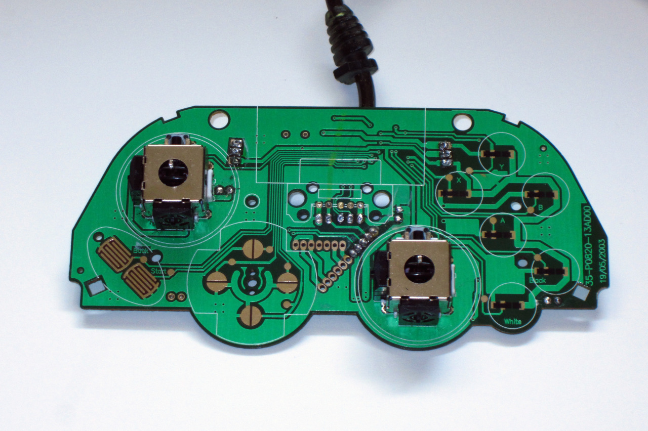
Here’s the pcb of the controller I plan to use.
Am I correct in thinking this is a common ground pcb, meaning I just need to solder a single ground point and then daisy chain all inputs to that single ground point?
I also notice that the buttons all seem to have circles (test points?) in addition to the normal button traces. Can I solder directly to those circles for the inputs?
I don’t plan to use the triggers, just the dpad, Back Start ABXY and Black and White.
The potentiometers you desoldered are were still providing some resistance. When not pressed the potentiometers or pots for short are still about half way.
with zero current, depending on how the analog was program you can get a full press or even a reversed input. The reverse input could cause the whole pad to malfunction until its corrected.
I don’t know the actual outcome as each brand and model PCB can be different.
Like what FattyWinnarz said you going to have to solder in resistors to simulate the not pressed signal of the triggers.
The circles on the traces are most likely test points for the manufacturer, and yes you can solder to them.
Wait…really? I’ve done padhacks before and never encountered that. Are you sure this applies to the original Xbox and not just the Xbox 360?
If the triggers are always active, then loading up an FPS, I’d be constantly firing and aiming iron sights, right? That’s not happening. I’ve already removed the triggers by desoldering and then breaking them off.
I also tried booting into CoinOps. In Copinops, the the triggers are used to very quickly scroll through the menu in either direction up or down. If you press them both at the same time, then it locks in place and can’t be overriden by the dpad or left stick. Again, that’s not happening. The controller appears to be treating the L and R triggers as if they dont exist, exactly what I’m after.
I’m almost positive the triggers were disabled when I desoldered and broke them off, but I suppose it couldn’t hurt to spend well under a dollar and buy two 10k ohm resistors to be sure the job is done. Where do I solder them…? please look at the pcb. The trigger solder points are the three solder points near the top of the pcb on either end.
I’ve never done this before, but surely soldering two resistors in place is a simple task. I just need to know -where- to solder.
Can I please get some help? I need to know how and where to solder the 10k ohm resistors mentioned.
Please refer to the photo of the pcb I posted. The triggers were those six solder points with three stacked vertically on either side of the top of the pcb. Do I…bridge the solder points together and then connect the resistor to both ends? I really have no idea.
where each trigger pot was you have a from bottom to top a +5 volts, a wiper and a gnd.
You want a resistor going from +5 volts to wiper, and sometimes you need a 2nd resistor going from wiper to gnd.
So you know where you desoldered the triggers, there’s three wires on each trigger. Do one from the top to middle, and one from the middle to bottom on both sides. Four resistors total for the two triggers.