It’s just another ground wire made from the outer metal shielding, it’s soldered to the metal casing of the USB socket. I don’t think it’s really needed, but I soldered it on there anyway.
If your’s doesn’t have the fifth wire then don’t worry about it. Mine had five as you can see in the photos.
I want to follow your guide to make my own VF5 stick aslo but I’m new so I have a Super noobish question: What’s the deal with the common ground thing, insofar that I don’t know the difference between the two. What’d be awesome (but maybe take u too long to answer) is a pic showing what needs to be connected to the “common ground”.
The only thing that needs to be connected to the common ground is one side of each button. Common ground means just that, every button shares the same ground connection. When you press a button, the signal from one side of the button is grounded with the other side (ie shorted out) and the 360 then knows what button you pressed. This setup makes it very easy to wire up as you don’t have to connect two wires to every button like you have to with the older M$ controllers.
All you have to do is connect one wire to a ground point and then daisy chain between the buttons so they all have a ground connection. The other side of each button obviously goes to it’s associated point on the controllers PCB.
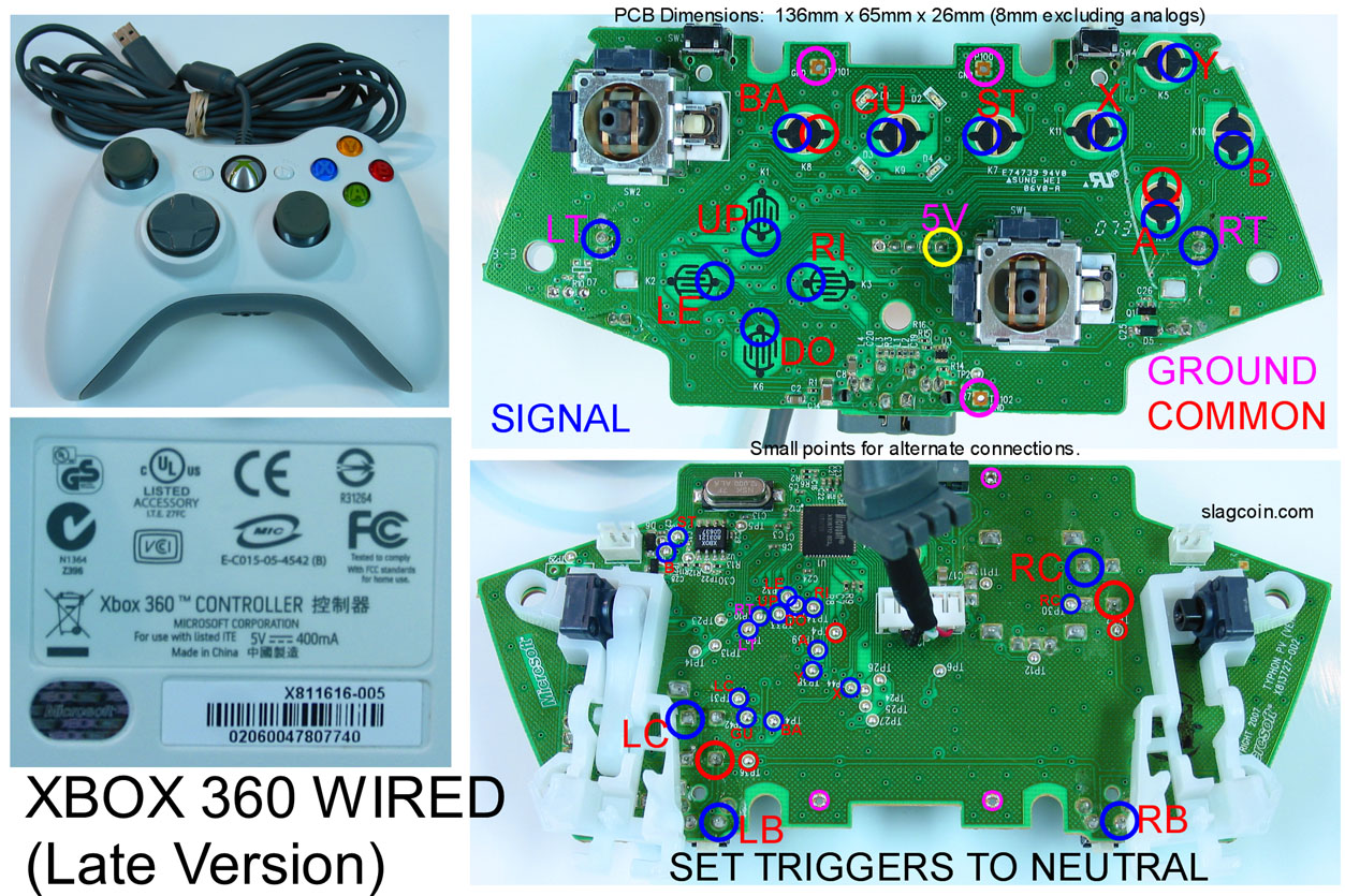
It’s not that difficult to understand, just as long as you have a multimeter so you can work out which side of each pad connection is ground. Or have a look at Slagcoin’s site and it shows you (at the bottom) what I mean in pictures.
Thanks a lot for answering the question so quickly it’s really helping me in getting a more confident handle on this. You last answer gave me insight in why my last joystick endeavor didn’t work, I hadn’t grounded things.
from the picture int he bottom (which is awesome) it looks like all the ground wires are strut to eachother except the one to the joystick and then put into the common ground. Now if I was to do this would I also need to have the joystick’s ground wire be part of the snake too?
How do you figure out which connection on the PCB is the ground (the anometer?) or did you just follow some diagram? I found the diagram for the wired 360 but have only seen your tutorial or wireless(which is awesome btw).
I noticed you said that removed the left and right triggers and soldered in a 10k resistor in each so you can use those buttons. Why did you even need to use a resistor to begin with, does that have something to do with setting the triggers to nutral?
Either use the same chain connection or solder the black wire (if you use a Sanwa JLF) to an alternate ground point.
You can either use Slagcoin’s diagrams or use a multimeter (set to continuity) so it beeps when testing two points on the controller PCB are connected. Multiple points that are all connected are your ground points. That’s how I found mine.
You need the resistor so the pad thinks the trigger’s still connected. It won’t work at all without it, plus you could damage your controller. I nearly smoked an original Xbox controller when I was mucking around not using a resistor.
Alright cool Been doing a lot of reading and I’m pretty confident I’ll be able to follow your procedure just a few more questions. (sorry for brining so many it takes me a day to soak in the knowledge and figure out things I’m shaky about, thanks for being so forgiving)
The play and charge deal you did; I see you took the PCB of it out so you could move the LED that lets you know it’s charging up into your Xbox guide button by using that guide you linked in your post. The second part of that procedure where you cut off the USB male side and replace it with the usb socket, how did you connect that deal up to each other? As in what wire connects to what on that metal box in the picture you showed, or does it not matter? I can’t really get a good look at that part.
Are you connecting the play and charge kit to the control PCB normally by just plugging them into each other like normal? If so could I bypass the whole step of breaking open my play and charge kit and just cut the other side of the cable so to turn it into a USB socket or does the curvature of the plastic get in the way of connections on the controller’s PCB?
The sync button you used was that the regular sync button that came with the controller initially and you just moved it and connected a wires to the respective spot on the PCB?
The guide button in terms of it’s actual function as a button, does it lose it’s ability in that respect when you move it out of the controller and serves more as a "what players # am I " function, hence you use another sanwa button to access your xbox guide screen?
Of course it matters how it’s wired! I used the USB pinout from this site. Also the LED’s in the guide button are 3mm LED’s, not the same LED’s that are on the P&C PCB.
It’s just plugged in. If you don’t plan on messing with the LED’s, leave the plastic cover on it and just change the USB plug on the end.
No, it’s a very standard push button switch you can find in any electronics shop. It would be next to impossible to use the one on the controller :looney:
I didn’t use another Sanwa button. Did you read the whole guide? The guide button works like any other guide button would, ie. it’s a fully functioning button. In fact I used the same type of push button as the one I used for the sync button.
i can’t seem to understand a couple of things about wiring the PCB.
I understand the common ground thing… what I do not understand is this: Is there one single common ground for all the signals? meaning one single ground for all the four directions and the four buttons and the shoulder buttons? (I don’t intendo to wire the triggers, too much work for my first stick)
Do you have to remove the black stuff form the soldering points?
Ok… so I have to solder one wire for evey signal contact… and just on single wire to the common ground… well two wires… one for the stick and one to daisy chain the buttons…
Me again… do you have any idea where the common ground is located in the wired 360 controller? It’s the latest model, just purchased…
So as to save time not testing every single point in the PCB.
Thanks in advance.
Cheers
Edit: I made a blotch… I accidentaly scraped away the copper terminal under the black stuff. I lost the soldering point for two pad direction this way… Left and up.
Is there any other soldering point I can use? If I follow the copper path… can I use another point along the way?
Ok… I found a couple of other point where I can solder… but they are so tiny I’ not sure I can make a correct solder without touching some other path or signal.
I’ll have to buy a new pad to get a fresh PCB.
But I have another question… if I take one wire form the 5 pin connector of the Sanwa Stick I received… and touch it to one of the signal point on the PCB… without closing the circuit with the ground point… That should not imput the signal right?
Cause when I did it the console reacted to the touch… I’m quite confused… I hope it was just some strange contact caused by the copper I stripped previously…
There is no common ground on the wired controller, it has what is known as a common line where the common connection has a voltage on it, something like 1.8V I think. Shouldn’t bother you however as you can hook the cabling up in a similar way.
If you’re careful, the tiny trace that comes from the pad can be scraped away and you can solder to that. Once you get a solid enough connection, use some hot glue to stop the wire from moving and ripping the trace right off the board. Try that first before shelling out for another controller.
That should’ve have done anything as there is no circuit. But God knows what’s happened to that controller PCB. You have to be very gentle with them, especially when scraping the black conductive material off the pads.
It might be safer to ditch it and start from scratch. Let it be a lesson :wgrin:
Then I’ll have a wire for every signal point and one wire for this common line to daisychain the buttons? Do I have to solder the ground wire of the joystick to this point too?
I think I have found it… it’s one of the solder point of the plug cable… the second from the left… at least yesterday it worked using that pint as ground.
Tried it, but it’s too fine a job… And I’m not that good at it…
I see… Well it’s a lesson allright… Next time I’ll be much more careful and precise. I cannot afford to spend 30 bucks every time I screw. :wgrin:
I just hope The problem I had with the stick wires it’s just some bad connections related to my ruining the PCB.
Yeah that’s right. You are wiring each button to a ground point and using the voltage line as your common connection. Think of it as a reversal of a common ground setup.
I don’t have one of those pads here so just to be certain, check the connections and make sure they all connect to the same point before you daisy chain them. Also, have a look here (courtesy of slagcoin) and see if your controller is the same. If it is, his connection points might help you a bit.
Wait a moment… so it’s the opposite of what I have done!!
My controller is the same one of the picture of slagcoin… I used it to find everything.
So I don’t wire the signal points for A, B, X and Y, but the opposite ground point? and use the common line point (in the slagcoin pic it’s the ground pink circle) to daisy chain?
No you misunderstood. You are doing the right thing.
What I meant was that with a common ground PCB, the ground is the common point, the one you daisy chain. With your PCB, you daisy chain the signal wire instead.


