Sweet… Thanks for the quick response Toodles 
Here’s to hoping that it is the easier of the two methods…
Sweet… Thanks for the quick response Toodles
Here’s to hoping that it is the easier of the two methods…
Is the left side of the transistor on this pic the collector?
http://picasaweb.google.com/wliu0912/PrehackedPads#5276551564936405794
Can anyone possibly see what i’m doing wrong. My pcb is the exact same as the topic creators and this method worked for him but not for me.
http://img8.imageshack.us/my.php?image=1000999y.jpg
I’ve tried over and over changing a few things up but nothing works when i plug in the controller and check to see if the button responds it never does. The only method that makes my LT respond is this single resistor method but this method seems to cause my A and B buttons to go haywire after about 5 minutes of playing.
What I’m seeing here is (from left to right) ground, signal + left leg of pot, right leg of pot, correct? And which PCB is that? All this inverting/non-inverting stuff is making my head hurt.
Will this work on the harder to hack versions of the pad?
I removed the diodes to simply test if I could get the 360 pad’s buttons to work and for some reason, only the left trigger works. I have this pcb:
From what I understand, each trigger needs one resistor. I used a 4.7 ohm resistor for each side. This is how I have both triggers set up right now:
http://con-trast.com/images/hosted/LT_wResistor.jpg
Again this is a dual pcb, so when I connect a wire from the common ground to the resistor, it activates the button. However, this doesn’t work for any other button on the controller. For all I know this has nothing to do with the triggers, but I am a total loss as to why none of the buttons work at this point.
EDIT: I tested the other buttons on the 2 other common grounds mentioned in the slagcoin image and those buttons seem to work with them. However, the left trigger only works with the common ground I am currently soldered into. The right trigger doesnt work with ANY of the 3 common grounds. I’ve really got no other guesses at this point and I’m hoping I don’t have to scrap this pad. Any help would be appreciated!
pictures please :bgrin:
Question about this. I assume (from what I’ve seen testing this in Windows) that you have to get both sides wired up before it will work, correct?
Second, does the other side of the board have it’s contacts in the same order, or is it a mirror image?
(I don’t have a multimeter, and people are only taking pics of the right side, heh.)
Thanks!
I really didn’t find this method to be too difficult. It requires no extra parts or a multimeter. I am in no way good at soldering, but if you just tin the wires (put solder on the wire, then take it and put it on the point, touch the soldering iron to it, done) it makes it pretty easy.
I took my POT completely off and bent up the ground (outside) connection. You could probably do it without even taking it off.

Don’t forget you will have to tweak the spinner until you can get it to register one button press, not several. Mine are glued down because I found my spot. This is not difficult nor is it as delicate as you would think.
Here is a close up of my right trigger connection.

Based on what I’ve done, it’s a mirror image (I don’t have a multimeter either). Looking at the board it should be.
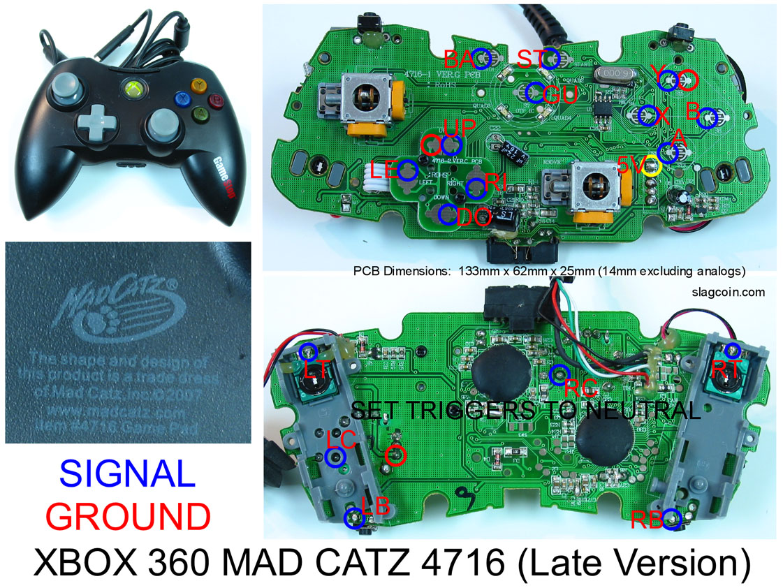
GROUND SIGNAL 3V ------------------- 3V SIGNAL GROUND
Confirmed, it is reversed. Everything working fine in SF4 now! Hooray! Thanks to everyone on this forum for the help; my shoebox stick is now working great. Next step: a real wooden box, heh.

Wow, I have a feeling I made a really dumb mistake. Could you do me a favor and look at the image I posted above? If the pot method connects the same points as the resistor method, I may have connected the wiper to the wrong pad, which could explain why almost nothing works! I may be slightly dyslexic…
A correct resistor/transistor method should look like this.
A correct POT method should look like this.
Yours looks like neither. The resistor method will use all 3 connections, the POT method only uses the inside 2 (3v and ground).
Heh, you’re using my labeled pic. Now I really hope I got the labels on the PCB side right, hehe.
thanks 4 labeling the picture dude…
I just wanted to say thanks to zombie-cpt for the trigger hack pics for the Madcatz Retro stick pcb. After I fixed my mistake of wiring the resistor backwards on the right trigger everything is working perfectly now.
Actually I have the 2007 pad so I only have to use a resistor for each. That’s what I get for using the wrong reference pictures 
I just picked up a newer, “harder” madcatz pad to put into my HRAP1. I want to keep my PS2 functionality as well. I’ve been through the first couple pages of this thread…and I am just curious: if I want to just not use the triggers at all…as in no buttons utilizing the triggers and just wiring the bumper buttons in their place, am I still going to run into an issue with the RT/LT? Do I still need to decide on a resistor/pot solution (On paper I can’t imagine I would…but I’m also not an expert)?
If you’re not going to use them, leave the pots on, make sure they are turned to the “off” position (test by hooking it up to Windows if needed), then hot glue them down.
So I tried the pot method since the resistors were not working for me, and now every button is working fine, but my left trigger continues to register as both triggers being pressed no matter how i turn the pot. Even with a stripped pad, the right trigger registers properly. I don’t see how I could have broken the pot. Does this sound easy enough to fix?