I’ve got a messed up Hori EX2 with swapped out Sanwa buttons and a Sanwa balltop + custom artwork… I’m having problems with some of the buttons working, so I’ve decided to just swap out the PCB and hook everything up in the existing case to a late version madcatz 360 controller…
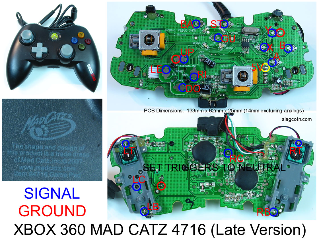
Slagcoin has a diagram here… but I need some help with a few things
What does it mean when it says “Set the triggers to neutral”?
Also, do I just assume where to solder the second wire from each button? I see that the first blue and red spots are labeled, but the rest are not… so I assume its just as pictured in the first example of each?
What do I do with the 5V? What do I wire from the Hori to it?
Another thing, what is RC? Also, do I only need to wire one wire from the RB/LB ? I don’t see two points labeled.
Finally, will the solder just stick to where the circles are? Do I need to do something?
Red is ground Blue is the line for each button as shown.
set triggers to neutral merely means if you want to use the triggers your gonna have to get rid of the pots for the triggers and set them to neutral via resistors
5v is the voltage line for those using optical joysticks; happ P360(or w/e its called dont remember), Sanwa Flash. Don’t worry about it in your case.
LC and RC could possibly be the Left control stick click and the right control stick click, on PS it would be known as L3 and R3 if you get what i mean.
You must be blind if you can’t see RB/LB as its labeled in the picture
Amazing soldering skills with keep the wire in place of where the solder is. Still, people would use hot glue
Next time look through slag coins site. After all that is where you got the pics.
Or instead of making a new thread you coulda posted in the absolute NOOBIE thread thats stickied
I’ll try and be nice since it’s looks like you’re struggling here.
Does your controller look exactly like that? If you bought it recently it may look like this. Take a good look before doing anything.
Just ignore that unless you’re going to wire the triggers. I know it’s confusing but don’t worry about it.
This is a common ground controller. It won’t have two wires coming from each button. You will choose one of the grounds: to the left of Up or the right of Y and run it around to every button.
You won’t be using this unless you’re connecting it to another controller or a stick you probably don’t have like a P360.
Yes, you’ll have one wire coming from every button.
Yes, mostly. One you get it to stick, test the point and hot glue it down.
I’ve got a question regarding ‘neutral triggers’ as well.
I realize I could save myself a lot of hassle if I simple remap the High Kick to the left bumper, but I also want to have a button that will trigger all 3 kicks/punches as well, which means I need to use the triggers.
However, everything I’ve read… . is just plain confusing. Is there a video out there that shows what needs to be done, or something for the technically illiterate?
Four quick questions regarding the modding and soldering of a Xbox 360 Mad Catz Late Version wired PCB. Please help cos I’m stuck !!
I know the PCB has a common ground but it still has 3 separate ground solder points ( the first next to ‘up’, the second next to ‘Y’ and the third on the back of the PCB on the right hand side of ‘LC’) - mt question is do I need to daisy chain all 3 together or can I simply choose 1 of them and ignore the other 2 altogether?
Also, if I wanted to ignore the 2 triggers (‘LT’ and ‘RT’) as all I need are 6 buttons - can I simply ignore these solder points entirely or would I need to use resisters to neutralise them?
Would I need to solder the ‘LB’ and ‘RB’ points from the back of the PCB or can I access the solder points from the front?
Will a wire harness from the stick work with this PCB or will I need to forget the harness and solder each individual switch contact at the joystick?
No you dont need to daisy chain any of the common ground spots together. You can use one on a button, one on another button, one on another etc and they will still work fine. If you want to only use one, daisy chain that around to all your buttons, if you would like to use two to keep your wiring a bit tidier, use two etc. Its all up to you. I planned on using one for my 24mm’s and one for my 30’s, but I messed up a bit and that didnt happen.
I ripped up a Ethernet cable and used the cables in there but I honestly wish I hadnt. Very very thin. Im sure everybody has there own personal preference but I’ll be going for something a bit thicker next time.
I cant really answer any other questions as I used a wired official 360 controller. If by wire harness you mean the 5 pin connectors that come with some sticks, you can just take the wire that is the common ground for that stick (Black on the Sanwa JLF, not sure about Seimetsu as I’ve never used one) and solder that to a common ground on your PCB. Then the other wires to the specific directions on the d-pad.
No its not incorrect. What I mentioned above was just stating he can use as many of the common grounds as he wants on his pad, and they dont need to be linked together to work. As long as your button has access to a ground or is receiving the ground from another button (daisy chaining) then it should work, unlike none common ground controllers which require a seperate ground for each button.
No need for a button that triggers all 3 kicks/punches, the reason they have this setting anyway in SFIV is for people who play on pads, so they dont have to do finger gymnastics, its super easy on a stick to hit all 3 punches/kicks.
