I figure it’s a long shot, but if anyone has already scanned this into modeling software (sketchup?) or can, easily, I’d love to get that file - it’ll save me a ton of time as I’m pretty new to this software.
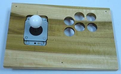
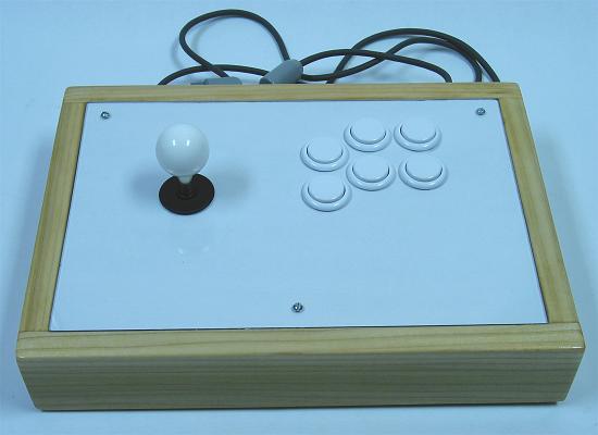
I am making a wood stick, so the joystick mounts from the underside and screws don’t show. That bracket is something I 3d print already, but it inhibits my ability to use standard ls-40 restrictor gates. I’m trying to modify my design by adding this part’s particulars to my custom bracket.
It should be pretty easy just to take measurements and draw something up in cad. You probably know your way around cad a bit if you’re building this custom part.
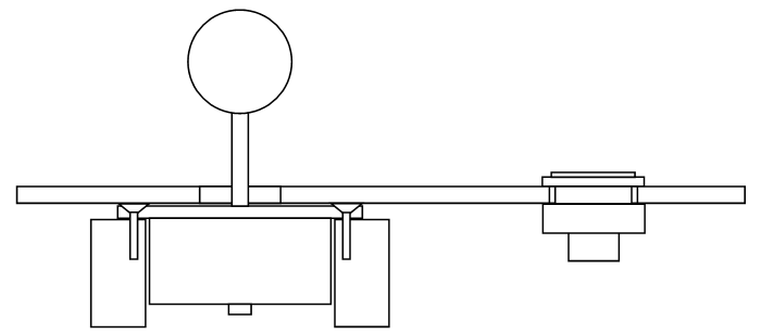
I think you are making bottom mounting harder than it is. You should be able to use two pieces of wood extending from the bottom of the case to the mounting holes on the existing mounting plate.
This is top-mounting the plate onto some pieces not attached directly to the control panel. Some precision will be necessary in making the heights work together. You may need to carve lightly a few grooves in the panel where the screws protrude, or warp or
grind the mounting plate so the screw heads are flush with the surface of the plate.
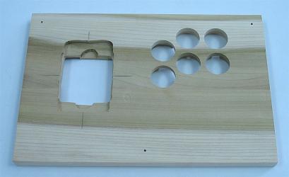
This is basically what I’m talking about. You would mount two pieces of wood from the inside surface of the bottom of the case extending upward so you could mount the plate on top of them. You then route the bottom of the top panel out so the joystick body fits inside. The main flaw of this style of mounting is that you need a hole in the bottom of the case to remove the balltop or you can’t take the bottom panel nor the top off. You could alternatively double layer the bottom panel so the bottom most panel is not the one the lever is mounted to. This would allow you to take that panel off to access the underside of the lever. There will still need to be a hole on the panel the lever is mounted to to get to the balltop. Or use a Link which isn’t an option for you with the LS-40.
Eh, I think I’ll go the CAD route. I’m a CAD novice so it just takes a painful amount of time for me… but I can’t use traditional methods for this project. My bottom panel is held on with magnets, so it can’t take the load of a joystick. The top has a small angel so it’d be hard to mount precisely anyway. I fasten everything to the underside of the top panel. Thanks for the suggestions, I probably should have posted some pics to start.

