I’m finally getting time to code for the LED board I made forever ago. Currently, everything appears to be working perfectly with support for either 11 light up buttons, or 8 light up buttons and a light up stick. The current code has a quick fade in and out of all LEDs when powered on, and the normal operation is a slow fade in when pressed, with a fade out when released. If the button is tapped, it won’t get very bright before it starts fading out, while if its held it’ll go to full brightness.
I could use feedback though. What kind of features would you like to see in an LED control board? Fade in when pressed, going immediately dark when released? Immediately on with a fade out when released? Boring on when pressed, off when released? Cylon/ Knight Rider moving lights regardless of being pressed? A button combination when plugging in to disable the LEDs? Set LED intensities for the buttons (i.e. Short and Jab are bright when pressed, mediums kinda bright, and fierce/roundhouse only sorta bright? If you have a wishlist, I’d love to hear it.
This one doesn’t have RGB control; with the rats nest of wiring it could end up taking, it didn’t seem worth it until I figured out how to get RGB LEDs that came prewired to 4 pin headers.
Everything’s ran by a single Atmega168; no other chips are present or needed. I’ve got a software PWM routine with a sweet queue system setup with it to minimize the current. If there are 4 led’s are 1/4 intensity, there will only ever be one LED lit so there’s a constant draw of current. If there are six LED’s at 1/4 intensity, then two will be lit at a time for half of the time, and one lit at a time for the other half of the time. There won’t be an ISP connector on this one, but there will be a spot for a six pin header for connecting a FTDI Serial->USB cable or equivalent. I won’t include the bootloader in the ones I make, but it’d be easy to throw in an atmel with a programmed Arduino bootloader and use the cable for coding. When I’m happy with the code, I’ll probably do any tweaks needed to use an Atmega48 or other pin equivalent but cheaper chip.
Wow these sticks are amazing… Would any of you be willing to sell these? If so what would be your price range? I’d pay over top dollar for one of these for the 360…
I’m very new to all of this, so my apologies if I’m asking dumb questions or questions that have been answered before. Any help would be greatly appreciated!
I was wondering what the difficulty of doing this was?
mmm i have NO knowledge of doing these kinds of things. I think the most knowledge i got was from woodshop back in highschool, and thats really not much of a help. When I look at the diagram/ pictures for doing this, im pretty clueless. BUT im not lazy, and im willing to learn. What are my chances of successfully doing this? and how difficult will it be? It would be kool to hear people with as little knowledge as i did, being able to do this.
Thats what I meant when I was pretty clueless to doing this mmm, i dont know what 1/8 w 220 ohms are, i dont know what a ground is, i dont know vcc, I like litterally have no knowledge on this kinda stuff. I think if i saw like a vid or pics of what im supposed to do it would be easier but im prolly not gonna get that. So im trying to figure out these schematics you guys drew out, but im am really clueless.
you think you can help me out? im on a sfiv mad catz TE
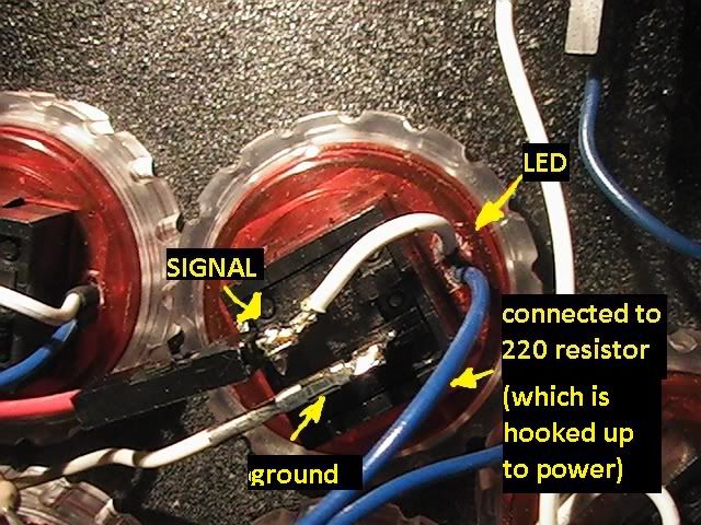
i’m not much of an enthusiast on electronics either, but the 1/8w 220 ohms is a resistor connected to some kind of power point on the controller(vcc) . and that circle with the triangle in it is the led. the led can only be connected one way so make sure it’s connected right or it won’t light up. and connect the other end of the led to the common part of the button. wow my instructions suck!! maybe i can post a picture of how mine is set up if you want. mine’s not a madcatz TE though. if you want it to light up on push your controller has to have a common ground.
naww bro, ur instruction are chill, you are at least helping me out, so i really appreciate that.
I’m first, just trying to figure like how the basics of this works. there are leds under each buttons. And for that led to light is to recognize that the button is being pushed. So i have to connect the led to the circuit board thing that also connect to the buttons. And all the leds need to be connected to an outside power source like a battery. Is everything I said right? what wrong? I wanna first understand if I have a basic understanding of this.
what kinda stick do you have?
yea bro, it would help alot if I saw a pic of yours. I would greatly appreciate it!!!
Hey i don’t have any stores near me that sell the parts needed for this so i need to order them all online… i was wondering if this stuff i picked out is the correct stuff needed for this mod. Also let me know if i’m forgetting anything or if there is a better website to get the parts from
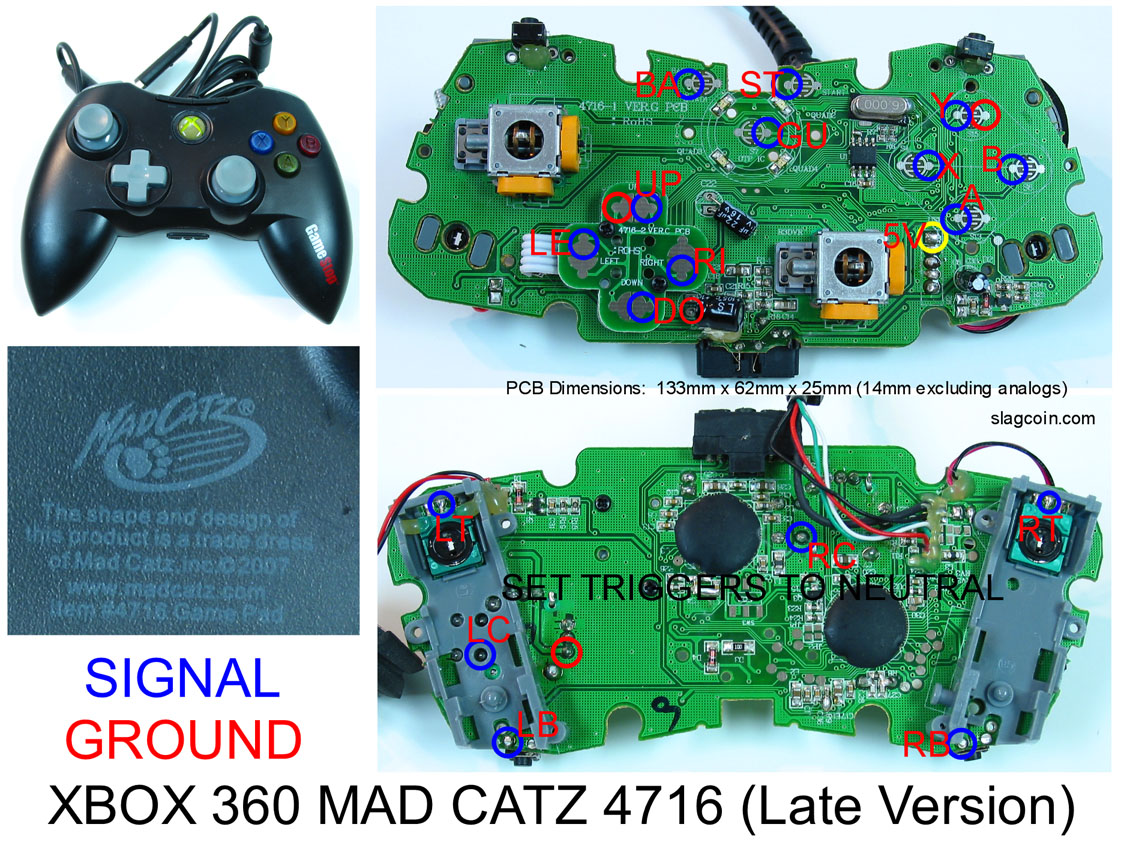
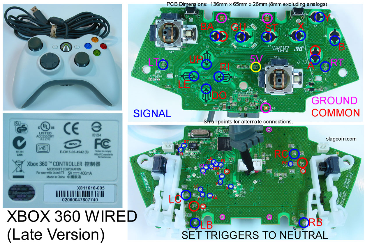
ohhh sorry man i don’t think i can help you on that one. the whole led to the circuit board thing i didn’t have to do. if it helps i made a picture of my set up
I was wondering what kinda buttons do i need or what do i need to get. I have the stock sanwa buttons that come on the mad catz TE. Do i need some kinda transparent ones? and if so, are there good buttons like sanwa that are transparent? I couldnt find n e transparent sanwas
So I want to tap into the 5V red power wire of the USB cable in the SE Madcatz Fightstick to power the LEDS. So I understand where the power needs to be attached to the HEX Inverter from this wire. But what do I do with the ground line that was supposed to come from the negative end of the battery to the HEX Inverter now that there is no more battery?
 with 32 general purpose I/O (8 buttons as inputs + 3 colors per = 32 exactly) no other chip required