Light-up on activation button mod tutorial

I’ve been reading through this thread and although i’m not a complete noob when it comes to electronics, a lot of its gone over my head. I’m planning a multi console setup using the mc cthulhu+X360+imp.

  1. Can i use 5v rated leds?
  2. Can i use this in conjuction with the above setup drawing power from just the console?

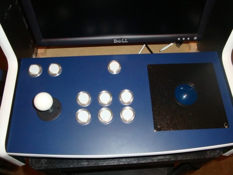
Experimenting with wireless light up

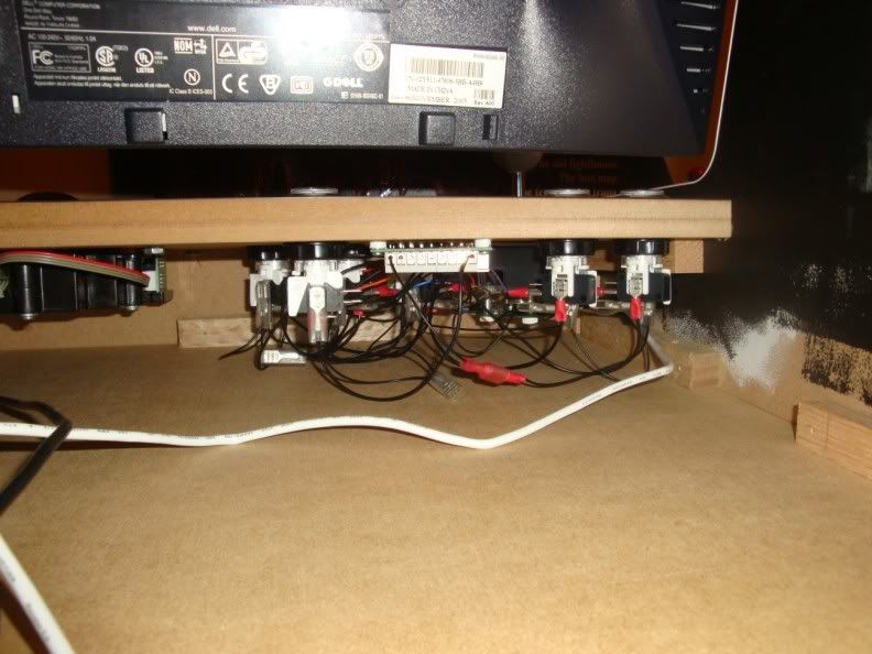
I did some experimenting with LED and the wireless pad with a rechargeable battery pack and I have some results. I hooked up the pad into a breadboard for prototyping/testing and using various LED to check out the brightness. Note that I have soldered on the points that taps off directly from the rechargeable battery and also tap a wire off the back button for demonstration. The battery output is at about 2.5 volts, and I didn’t use any resistors on the LED. Also the wireless pad is an official Microsoft common ground.

The first two images I am showing you are how bright the LED are with a fully charged battery pack… also they are lined up in parallel.

http://img523.imageshack.us/img523/8527/picture0102led.jpg

The LED here are 5mm diffused color… I don’t know what the exact forward voltage are on these because I bought them in an assorted pack at Radio Shack and they don’t list the specs in their packaging. Other than that, they are fairly bright.

http://img146.imageshack.us/img146/341/picture0304led.jpg

The LED here are 5mm clear lens that I bought from eBay… the LED colors are from left to right: white, yellow, blue, green… I didn’t put red in there because they would burn without a resistor. The yellow is the brightest because the forward voltage is low compared to the white, blue and green. The white is the next brightest and the blue and green are fairly dim. I tried a violet/purple LED, but they barely light up.

The next two images I am going to show you are the LED hooked up to the circuit with a push button to light it up.

http://img151.imageshack.us/img151/9188/picture05led.jpg

First picture show the controller is off, but the push button LED are still on. There may be another way to hook it up so that the push button LED will be off when the controller is off, so if anyone can share any insight to this then please reply. Otherwise, the only solution I can think of would be to put a toggle switch to turn on/off the push button LED so that it will not drain the battery when the controller is off.

http://img32.imageshack.us/img32/5589/picture0607led.jpg

This next image shows the controller is on as you can tell by the ring of light illuminating… please note that the push button LED is off once the controller is turned on. I tapped a wire off the back button and used a tact switch to demonstrate the light up with push button… as you can see it works as normal.

Well, I hope my little demonstration can provide some help for people who want to do a light up for the wireless joystick. If you are planning to use LED that requires higher forward voltage (e.g. blue or violet/purple), then you might have to find an alternative power source such as a dedicated battery.

The reason the LEDs are on when the controller is off is because of the inverter. The inverter takes a 0 signal (off) and changes it to 1 (on). So when your controller is off it’s not sending a signal to the inverter which means that the 0 that’s being sent is being changed to a 1.

Either you can use a toggle switch or a transistor, both of which are shown in the first post.

This is the toggle switch schematic

This is the transistor schematic:

Look at Q1, it is kind of an electronic switch. When a signal is received at pin B (a 1) the “switch” between pin C and pin E is closed so that current can flow through it.

For more information on Q1, look at idea #2 in this:
http://forums.shoryuken.com/showpost.php?p=4814275&postcount=33

  1. Never heard of 5V rated LEDs. I’m sure these are just LEDs with a resistor already attached. Normal vf for low-power LEDs is 3.2-3.6V for white/blue and 2.2-2.8V for red/amber. They should work fine.
  2. You could probably do it without batteries. USB ports are supposed to provide 500mA, I don’t know how much the Cthulhu or the X360 pad take but I’m sure it’s negligble. for 3MM or 5MM LEDs you are looking at 20mA per LED. You would have to take the 5V and ground lines directly from USB. Use the USB +5V in place of the battery + and use the USB - (ground) in place of the battery -.

I will be attempting this soon, but I have a question about a similar mod I plan to try:

Is there a way to add “ground fx” to my case? Not just a constant light, but say a slow pulse effect?

What would I need to buy/research before I try that?

You are looking at programming a microcontroler.

I was planning to use these LEDs and these buttons as they’re essentially made for each other so to speak. It would remove the task of drilling holes in buttons for normal leds. I was just looking for a shortcut here as my project seems to be bigger than i first anticipated.

I don’t see any issue with that. It should work fine.

These are ultralux buttons from Andy at ultimarc. I have a set in my bartop cabinet and they work great. The buttons themselves are definately stiffer than sanwa or even happs buttons though, so they take some getting use to. Also they will be larger than typical sanwa buttons, so I don’t see them fitting in a normal japanese case. Otherwise they are easy to install and I’ve been very happy with them.

Same switches that are in the JLF/JLW aren’t they? They’re pretty nice.

Thanks for providing the links, it helps alot… didn’t realized it was on the first post :sweat:. For the transistor method, do I use a resistor with less resistance than the one that is shown in the diagram since I am working with 2.5~2.6 volts off the wireless pad? What value resistor should I use?

I believe so, I just know the lenth of the button is close to a happs when installed. Here are a couple of pictures of what they look like installed and a video so you can see the effect:

You can see the depth on a 3/4 inch mdf panel here:

http://i78.photobucket.com/albums/j81/stephenp1983/blue%20bartop/th_lights.jpg

I think it would be fine with the same 5k and 20k ohm resistors. You’ll have to change the 220 ohm resistor though. http://led.linear1.org/1led.wiz to calculate your new LED resistor value.

Cheers for the info. I suppose i’ll try one first. I cant imagine buttons being stiffer than Happ.

Hmmm…I’m trying to do this with my Madcatz PS3 SE stick by drawing power from the USB. I can hook that up fine and get 5v when I test the Vcc and Ground across the inverter, but I get almost nothing on my LEDs when I press a button. I tested the voltage, and I get a mere 0.14v when a button is not pressed and 0v when the button is pressed. I’ve basically got the power going straight from the SE PCB to the circuit, so I’m not sure what’s up. I’ve tried putting in the wires the other way to no avail. Is it my chip? My inverter is a DM74S05N (datasheet here: http://www.alldatasheet.com/datasheet-pdf/pdf/51099/FAIRCHILD/DM74S05N.html )

It looks identical, but maybe there’s something different about it that I’m not aware of…

Alright, put up a pic of what my circuit looks like right now. I’ve got voltage and ground coming from the Madcatz PCB, just working on the one button right now. I’ve checked time and time again, I’m certain it’s correct. After looking at the datasheet for the inverter I have, it doesn’t look like I’m going under or over the voltage it’s rated at, so I don’t know what’s going on. I can get the LEDs to light up if I go straight from Vcc to the line the resistor is on, but it just seems like the inverter isn’t doing anything…

http://img44.imageshack.us/img44/74/img0279r.jpg

Make sure that you have the VCC ground going to the correct pins on the chip. Also test that your resistor is not too strong. Use the resistor in line with the LED and touch them to the VCC and Ground off the USB if you get light you’re good. If no or little light then the resistor is strong.

XFD just realized what my problem was. I had both the signal and ground wires going to the inputs of the inverters. Separated those, and voila! How the hell did I miss that in my hours of troubleshooting?:grrr:

Okay, got it wired up and my stick back together…now I have a really annoying problem…my buttons work, but they only register an input after I DEPRESS the button. I get nothing when I push down on the button, but when I let go, I get the action. What’s going on here?

Man, I’m just answering all my own questions tonight, aren’t I? Just tried Andy’s method from the previous page, and now the LEDs and stick work perfectly!

I’m confused to be honest. I really don’t know which method to use (Andy’s or Tingboy/Toodles’). Andy’s does seem infinitely simpler though.

I’m a real noob at this so please bear with me. I understand the circuit diagrams for the most part except for the Q1 thing in this diagram (http://jerome.mathevet.free.fr/shoryuken/TingBoy_LightUp2.png). Does someone have a picture of this actually wired up? It would be nice to see how it’s actually done. It looks like the wiring would be really messy. I’m not even going to try to explain how I think it works. Lol.

Andy’s method seems much simpler though and something I understand with my rudimentary knowledge of electronics.

Let’s say I’m using the Mad Catz 360 retro stick and my LEDs are 3mm red ones with a forrward voltage of 2.1v and forward current of 20mA. I’ve used an LED calculator that says I would need a 150ohm resistor for each LED given the PCB voltage is 5v apparently. So I would solder a wire to the 5v on the PCB and connect it to the LED with the resistor inline and then connect the LED to the button signal and the button to the common ground? That seems far too simple. Lol.