SWEET
would love to have the schematics n hex … PLZ:lovin:
really nice work!!!
SWEET
would love to have the schematics n hex … PLZ:lovin:
really nice work!!!
very impressive, thats amazing, I’d love to get some info from you on how to just do the stick in color change, and have the face buttons ever lit. Not needing the side LEDs, but very impressive looking on yours!
Thanks!
Okay, the stick is a LS-32 with a drilled shaft and drilled ball. Here’s is little pic tutorial in my blog
Then I’ve soldiered a rgb smd led.
http://2.bp.blogspot.com/_YLXgzxS8cEc/SRn2xYwRLAI/AAAAAAAAAIY/qen0cynBeMA/s320/P1020923.JPG
Size was here 0603, probably there is place enough for 3mm.
Then assemble all the parts together:
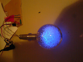
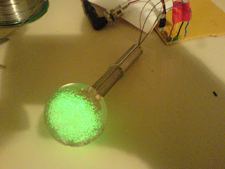
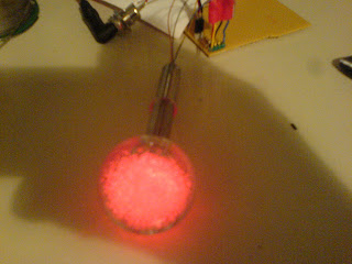
And make some tests.
Then I’ve programmed a Atmel ATMega8 to do the lighting job. This was the easiest way for me and I could add some functionality for the led startup attract mode and Case Lighting. Schematic and Hex will be published soon.
bencao74, do you get any problems with wire twisting/tangling inside the Shaft?
I have a drilled Shaft, but I don’t play with the LED in, for worry of wire twisting.
Yes, of course I’ve this problems. Speedsterharry posted here a nice solution. But this doesn’t fits in arcade sticks…
Oh yes, I saw that.
Thought was really cool.
Was just wondering if you found another way to prevent twisting.
Hi,
okay, here’s the schematic:
http://2.bp.blogspot.com/_YLXgzxS8cEc/SgQq342g-LI/AAAAAAAAAiU/oyx3FqkKZa0/s1600/led%2Bmod%2Bbencao.gif
Source is linked on my blog. It’s a quick hack. IDE was AVR Studio, programming SW Pony Prog. Shown schematic has no programming connector. There’re tons of tutorials to do such a programming board with parallel programmer.
Mod was with a common ground xbox360. Use this solution for making out of non common ground controller a common ground one.
Thanks for posting this bencao74. I am also using AVR Studio and ATmel chips. This will help me down the road with more custom LED mods for my customers.
Michael
Hi Michael,
 it was fun. Next time I’ll take a deeper look into PWM to dim out and in the leds…
Bye,
OMG I have been looking into doing just that, let me know how things work out, and thanks a bunch for all the helpful resources on the subject!
Aaron
Hi,
I’ve done yesterday a button led mod. I’ve used 2 led (20mA) for each button. I’m making a 8 button layout. Thus I’ve 16 led a 20mA, summarizing 320mA.
Led mod is for xbox360, power is taken from USB which gives 500mA. 500mA - 320mA makes 180mA. Is this enough for the PCB to work flawless? Or can I add some more leds?
I’m not sure if this kind of question arose…
USB is required to provide 100mA. The USB device itself can ask for more, up to 500mA, but the USB host does not have to provide it.
With that said, the pad itself probably uses no more than about 20mA, unless the vibration motors are active or the four status LEDs were still on, in which case I’d figure in another 20mA for the LED. So, you can use more, but it may cause problems.
okay, then I’ll reducing case lighting to 5mA or 10mA at maximum. Thanks for this info
Will USB provide enough power for a dual pcb (HRAP3/xbox360) + 8 led mod? I see posts that talk about it, but there doesn’t seem to be any posts where it was actually done.
Any input would be appreciated :bgrin:
I would also like know that as well. I wanna do a dual pcb with light mod too and use power from usb. Gonna go Cthulhu ps3/xbox 360. I wanna do 8 buttons but was hoping to do the ball top as well.
Does this mean you won’t need to use a resistor between the inverter pin and LED?
I know nothing about circuitry and electronics but I would really like to add a simple LED mod (at least it sounds easy) in my sticks. I was hoping I could provide some details in the hope that someone with the right experience/knowledge can perhaps provide a drawing (like the ones on the first post) which I can then follow.
Ok, What I’m trying to achieve is 8 LEDs that power on and off with the wireless 360 PCB but draw power from a 9v battery.
I currently have:
I’d be willing to purchase additional parts if needed.
I know I could do a similar mod using a on/off switch but I really would like the LEDs to go on and off with the pcb without making it so I’d need to recharge every hour or so.
Any help would greatly be appreciated. Thanks in advance.
First off thanks to everyone whos contributed to this thread its been a major help for me on my current project.
Just a quick question. Suppose I was wanting to do a light up on activation mod, but only wanted 2 LED’s, one for the stick and one to cover all six player buttons? So far I’ve been following Kaytrim’s tutorial on page 4 (I think), and I’ve done a quick diagram of what I think would work, though I could be WAY off.
excuse the crapness…
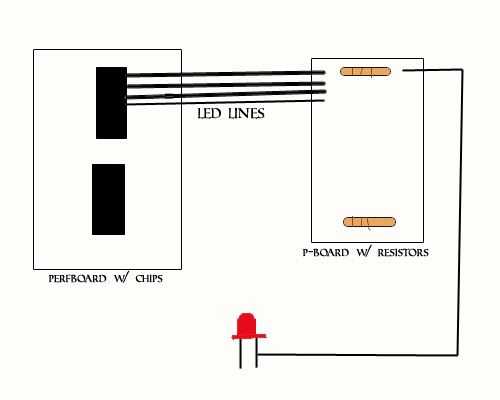
I was basically thinking of bridging all the LED line connections on the second board and then thru the resistor?? Is this the way to go or will I still need a resistor per line?
hopefully you can understand my drawing and thanks.
G.
***In case this makes it any clearer… I am going to have to bridge my wires to my LED at some point. Should that point be before or after i hit the resistor(s)?
You need a different chip to get the joystick to do what you want. If the joystick is on a diagonal it activates two of the switches. This could send twice the voltage to the LED and burn it out or cause a short circuit. The chip you are looking for is a 74HCT20. This is a 4-input NAND gate logic chip. Connect the joystick directions to pins 1,2,4,5 your resistor + LED would connect to pin 6, VCC to pin 14 and ground to pins 7,9,10,12 & 13. You can see the datasheet here.
The way this chip works is if any one or combination of inputs are high then power from pin 14 is sent to the LED on pin 6. If all four inputs are low then no power is sent to the LED
Michael
That makes perfect sense, I will try and get my hands on a couple of those tomorrow.
Thanks for the quick response mate, it’s greatly appreciated.