In addition to my previous post, since the HRAP EX is not common ground…should I just stop now? When you open the controller, on the bottom side there are 2 ground wires. One is attached to a screw holding the cover plate with a screw mount. The other has a screw mount but just floating. Am I in over my head? Probably but again…help or advice is welcome.
I’d use analog switch ICs rather than inverters. The reason people respond with “you can’t do it” is because if you have to ask then you most likely can’t do it with your level of skill.
Thanks to the original posts from Tingboy. There has been debate on whether or not the LED mod was achievable on the HRAP EX for Xbox360 since it was believed not to be common ground. This was my first attempt at wiring and I honestly still don’t know if this stick has common ground…all I know is that whatever I did worked. Nobody really helped answer any of my questions perhaps because no one is using this stick. But if anyone has any questions for me I’ll be happy to answer them.
Here’s a vid of the buttons in action and some photos:
Video:
[media=youtube]qOQEp_lmwBQ[/media]
Photos:
I tried to be as non-destructive as possible. I retained the QDs going to each button so in case some thing went disastrously wrong I could easily revert back to the original wiring. Also, leaving the QDs makes it easy to swap out for new buttons.
From what you and I read, the HRAP EX is believed to be non-Common Ground.
I don’t have one, so I can’t check.
But you were successful in doing this LED Button Mod on HRAP EX.
I see that you used two 7404, because one 74HCT04N can only take up to six Inputs.
And well you have eight Buttons, so you used two 74HCT04N, each doing four Buttons.
That was how Kaytrim did his 6+ Button LED; using multiple Inverters.
I think with your skill level, you got the HRAP EX to work.
Like how Esker said:
In response to “can’t do” to a non-Common Ground without more work done.
Like making a non-Common to Common using Optocoupler, or 7404 Hex Inverter and 4066N Analog Switch.
I’m going to stop typing.
I forgot how I wanted to go with this.
Laugh.
So good work M00_66.
You and I same on status of HRAP EX PCB.
But you did what you did, and it worked how it work.
I just reread my Post, and I don’t even understand what I typed.
Laugh.
Thanks for the comments jdm714. It’s funny 'cus I followed Tingboy’s wiring and the only real difference is that the buttons are not grounded by daisy chaining. This is literally the first time I’ve ever wired anything this complex. The only other thing I’ve ever done is change pickups in a guitar but that’s much easier. I think this is proof that you don’t have to be a pro to do something like this and it certainly demystifies the EX non common ground issue.
And again since I am basically a wiring noob, I made sure that this mod was not very invasive at all. There’s still a lot of soldering but if you practice on spare wire, you’ll eventually get over the fear of cutting and soldering wires. Really…you can always reconnect them and essentially go back to the original setup.
Sorry for the late reply Thanks for the input, it was very helpful!
I’m planning to buy parts to start this project and have a couple of questions based on further research:
Ok, so I’m modding a MCatz 360 SE (who isn’t, right). I plan on doing the Cthuhlu + Imp mod, with this LED mod, should I do one then the other or try to do them simultaneously? My thinking is to get the Dual mod up and running then add the LED mod…but I want to be efficient with my soldering.
If that wasn’t enough, I also want add a light-up stick with activation when not in neutral as mentioned here:
Since I’ll have 8 buttons with LEDs, I’ll be needing 2 hex chips, right? So, do I still need the 74XXX20 for the stick directions? Or can the remaining pins on the 2nd hex be used for this function?
Since the dual mod is probably most important, I would do the dual mod first, and just make sure your dual mod includes ways to easily tap into the signal lines. Then after your dual mod is working, then start with the LEDs. Frankly, using the inverters to drive the LEDs can easily be pictures as another console pcb All of the requirements for dual mods are the same requirements and procedures for getting the dual mods done.
You know you need to connect all of the signal lines and power and ground between the two pcbs, and you’ll need to also connect them to the inverters for the LED mod. You just need to plan out how you can easily do that.
I’d expect probably one of the cleanest ways to do it. would be barrier strips. (That I can describe there are other ways that wouldn’t take up as much real estate inside the box, but I’d have to start digging up part numbers and stuff) Use a barrier strip to connect all of the signals (all of the buttons, directions) and power and ground between the two boards. Get your dual mod done. Then when you decide to add the LED mod, you can tap the signals and power just by sliding a wire into the barrier strip. By doing one before the other, you can work out the kinks with less variables to deal with. If the dual mod doesnt work before the led mod, then there is no way you could get the led mod working.
For 8 light up button activated LEDs, you do need two hex inverters. One hex inverter can handle only 6 each.
Thanks for the clarification :woot: Yeah for the 3 PCB mod :wow:
Got it So what about the 4 stick directions lighting up on activation? You mentioned the 74XXX20, is that still necessary with 2 hex inverters, since I will have spare pins leftover?
Very informative thread!
I would like to keep it simple and just add 4 LEDs that stay on while the controller is on (360 wireless common ground). I also wanted to use a separate power source (was gonna throw in a 9v battery along side the 2AA the controller uses).
I know I wont need an inverter and I can just wire the LEDs to one another with a resister which originally I had planned wiring an on/off switch for the lights but I would love to somehow set it up so the LEDs come on when the controller is turned on and go off when its turned off. Anyone know how I would go about doing that?
On another note, I wanted to also keep the 4 green LED functionality the controller has (the ones around the guide button), could I just connect 4 other LEDs to the points thereby allowing me to position them how I like? If so, what kind of LEDs should I be looking for (I assume they’d need to be similar power wise to the ones already there)?
Any advice would be greatly appreciated. Thank you.
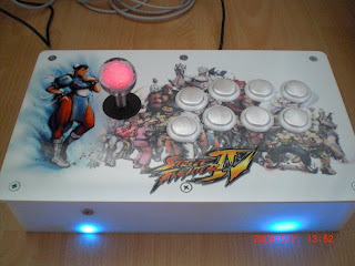
I’ve made yesterday a little led mod for Boilers Stick. The case has four blue Leds in the corners and led ball has a built in RGB smd led. When stick is moved the color in the ball top changes. Additionally the corresponding corner according to the direction pressed are lit up.
No Movement: Ball Top is RED
UP & DOWN : GREEN
RIGHT & LEFT : BLUE
LED mod can be switched of by pressing start + select and up.
Led Attract Mode when Stick is connected to console. See the [media=youtube]M5qIRRzKrns"[/media].
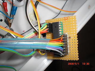
Here’s the breadboard.
If someone is interested I can post the schematic and hex.

 All of the requirements for dual mods are the same requirements and procedures for getting the dual mods done.
 So what about the 4 stick directions lighting up on activation? You mentioned the 74XXX20, is that still necessary with 2 hex inverters, since I will have spare pins leftover?