roughly about 2$ cheaper  and probably easier to build up, because one optocoppler for each ground line plus resistors.
Nice, when I get lack of Madcatz Controllers it’s worth a try!
roughly about 2$ cheaper and probably easier to build up, because one optocoppler for each ground line plus resistors.
Nice, when I get lack of Madcatz Controllers it’s worth a try!
i dont know about electronics that much but i think im getting the hang of it, but about components im in blank, so doing a research
will this do?
http://cgi.ebay.com/ws/eBayISAPI.dll?ViewItem&ssPageName=STRK:MEWAX:IT&item=280289756249
and the hex converter?
http://cgi.ebay.com/ws/eBayISAPI.dll?ViewItem&ssPageName=STRK:MEWAX:IT&item=220339192567
thanks
For my application I use smd size 0605 , but that’s not easy to soldier. I recommend 5mm or even 3mm super bright Leds. You’ve linked 8mm leds. Thats really big for built-in in buttons or similar. In this thread is a solution without IC. However… don’t forget the resistors
thanks for the info, will look for 5 mm leds, and dont worry already got the resistors :wgrin:
Is this mod impossible when using pcb’s with only one ground?
Yes, it is only possible with a common ground.
Curious how long does it take to do this mod & how much is the estimated cost…
It cost me about $12 with the barrier strip. I also already had a soldering iron handy.
As for how long…if you’re not too experienced with soldering small objects, then 4-6 hours, otherwise 2-3 hours
This does not make sense. You mean it is not possible with a full common ground, right?
Heh, both TraitorAI and I misread your question the same way.
So, to answer, the mod described here requires a common ground pad.
Oh, ok, I understand now. When it said “Unused ground” I thought it meant a ground that does not connect with the ground used for the buttons.
Hey guys,
I used an alternative design suggested by Bencao on my 2P panel (thanks mate !):

and here’s a sample of the result:
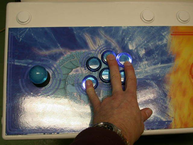

I was afraid the combined currents drawn from the USB port would make Windows disconnect the device but apparently not, so I’m a happy bunny now !
cool without a hex inverter.
what pcb are you using (madcatz 360? PS3?)
also whats the specs on the LED’s you’re using (forward voltage etc.)
The PCB is one for PC (common ground, noname). The panel is connected to my unfinished mamecab. Regarding LEDs Vf, I have no idea, I didn’t take any voltage measure, I figure they are rated between 3.4 V and 3.7 V…
EDIT: Certainly not 3.7 V, this sort of voltage is for power leds… let’s say between 3 and 3.5 V
ok thx for the reply. The design of the stick is cool btw.
Is there any disadvantage to using this method? Why would anyone use the one in the original post over this?
any idea how this would look with those buttons:
http://akihabarashop.jp/developments/images/seimitsu-PS14GN-clear.jpg
solid color, but clear plunger
http://forums.shoryuken.com/showpost.php?p=5764107&postcount=163
Depending on the pcb, wiring it up that way can have an affect on the pcb. The input of an inverter can’t, which is why it’s been so reliable. Definitely feel free to try, but it won’t work on every pcb. Using an inverter makes it very ‘hands off’ and doesn’t disturb the console pcb.
huh, that’s curious. even if the voltage from the led was high, the only thing it would be connecting to is the signal from the board right? (I thought that was a one way street, maybe you can put a diode in between?) What I mean is, that led/signal is not connected to ground without the button being depressed, so how can this happen?