Hey, I was quite amazed when I found out you could actually make a arcade stick from arcade parts which are connected to a sacrificed controller PCB.I’ve been trying to figure out how to do the electronics of a arcade stick using a model 2 Saturn controller PCB. I think I have it figured out but I’d like for more people here to confirm that this is indeed the right way, since I’ve never done any electronic soldering before.
This is going to be a 8 button stick, since I do need L and R buttons on my Saturn stick.
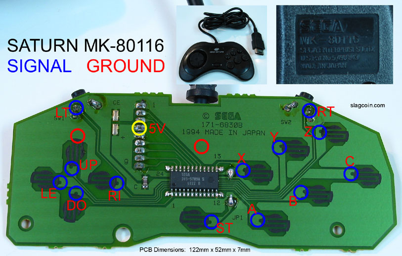
http://img22.imageshack.us/img22/3617/saturn04.jpg
I will gently scratch off the upper layer on all the little notches where the diagram mentions and solder on signal wires. Plus a single wire attached to the pin mentioning ground on the second diagram for a ground wire (thanks kyle!, The second diagram is his).
Then I will add a second set of signal wires to all the arcade buttons and chain a single ground wire directly between all the components.
A third set of signal wires will be connected to an assembled FGWidget LED chip, both to receive and to light up LEDs. Plus one VCC wire and a Ground wire.
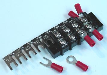
The the wires of the arcades will be added on a single (let’s call it input) side of a terminal strip. on the other (output) side, the corresponding input will go to the wires to the Saturn PCB as well as the input of the FGWidget chip. As slagcoin shows that using terminal strips is great for connecting one wire to two others (as well as making your wiring neater).
To power the FGWidget chip, a direct connection will be made to go from the 5V pin on the first Saturn PCB diagram, otherwise all other ground wires will be connected to the grounding pin by being on the same connection through the terminal strip.
Am now reading up on how to use a multimeter to check connections and make sure I’m not shorting anything out and to check if the 5V pin mentioned is actually the VCC and that the Ground is the actual connection to the ground.
I tried finding this all out but I’m not sure if this is the way to go, I hope someone more experienced can check this over and confirm if it is the way to go.