ulao: PS. if you don’t have a logic analyser or descent 'oscope it’s going to be very hard for you to do it.
The latter. Defeating the security stuff is way beyond me, and probably way beyond even seasoned cryptologists.
My goal is to take a controller chip from a 360 pad, which includes all the security stuff, and solder it on to my own PCB. I can then put screw terminals on the PCB so it’s easy to work with, unlike a pad hack.
You know I didnt factor that in , it does need both lines for comm… I do have room in this case I upgraded to a biger chip recently and now have a lot of room. I may give this a go then, thx for the replys.
yeah no analyzer here. I do have a very old scope that has good ability left in it, however no console… I know you wish to keep you effort disclosed but any help would be appreciated. Or , just wish me luck.
But the MC Cthulhu already does those at a pretty low price point…
The real achievement would be making one board to do PS3/Xbox360 (even if it needs the security chip), DC, PS2, and GC. I think the Dreamcast support would be the “new” thing added this way, and he’d have something that has an advantage over the MC Cthulhu.
I’d say the more open source arcade controllers around the better. If you don’t want to do the PCB design, I would be happy to help out in that regard. If you make your schematics and design considerations open I could lay out the boards for you. Heck i’d lay out several form factors, its relaxing, lol.
I’m also curious as to what micro you are using for this project if you don’t mind sharing.
Guys, I have managed to solder the chip on to a new PCB but am having trouble getting a computer to recognise it. It’s very hard to trace everything back by hand and figure out how to connect it up.
If only a datasheet was available, but I expect there is little chance of getting one out of Microsoft…
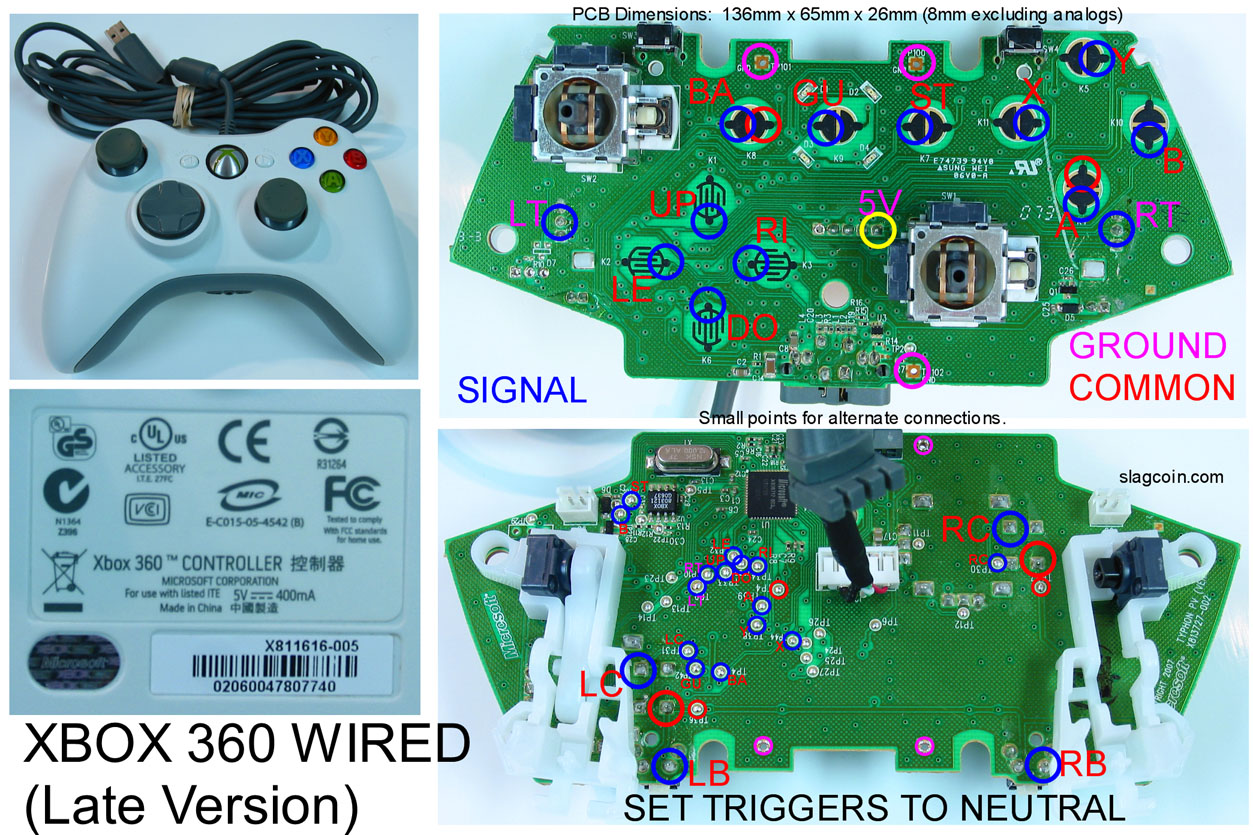
I’ll keep at it though. The theory is fine, it’s just a case of making it work in practice. I am using a chip from an early 360 pad, but looking at the later design it might be easier to use one of those. The layout is a lot simpler and easier to work with. If anyone has a broken late revision pad they wouldn’t mind letting go of, I’d be happy to give you something for it. The late revision pads look like this:
(note the sticker design, the early revision does not have any Chinese characters or “5V 400mA” on it)
If it can’t be made to work, I thought of another way using one of the new USB OTG AVRs.
Just to re-iterate, I’m not in competition with anyone, not looking to get rich. I was doing this as a hobby project and just thought it might be of use to some people.
Just to clarify, for XBOX 360 support there are two options:
All-in-one PCB with 360/PS3/PSX/USB/etc, would need both a 360 controller chip and a microcontroller chip
Separate 360 and “everything else” PCBs
I would probably do the latter, and have them stackable (one clips on top of the other, like Arduino shields). That way if you only want the 360 bit, or only the “everything else” bit you can get just that.
I have decided to make the DC stuff open source too.
The chip powers up and I can see some activity, but it does not recognise as a USB device. I think the clock signal isn’t right, but the way it’s wired on the 360 pad is unusual (seems to be series mode). I might try just using an IC to provide a 12MHz clock.
The design of the newer pads looks a lot simpler and easier to work with. The IC has fewer pins too, which means less work figuring it out and providing support circuits.
That still sounds like a great idea, if it works like that I’d definitely use this for my second controller I’m working on (in the idea stage at the moment).
Keep up the amazing work, and keep us posted!

