i’m making a wireless 360 stick but i’m having issues soldering to the d-pad spots. are there any other spots that are easier to solder to? like on the back side or anything?
I just tried soldering my first 360 pcb. I succesfully removed all 4 copper points while trying to solder on it x.x! I resorted to soldering on the back alternate points. Worked much better, and with the points already having solder on them all I had to do was tin the wire, and touch the iron to the spot, and touch the wire to it and it sank right in. Jst be extra carful since they are so close together. Don’t use too much extra solder or you may link the points.
alright, i was able to solder to the dpad spots on the back. much easier than the front contact points.
i haven’t been able to test it out yet because i haven’t decided on how to power it since it’s wireless. i’m going with either hacking a play and charge kit. or using a battery holder. any suggestions with this?
i’m using an old 360 case for my stick. i’m trying to integrate the rear usb port if i go the play n charge kit route. i’m also using the on/off button on the face plate as the guide button. still trying to figure out how to make the lights on the faceplate function like they do on the controller. also wiring up the sync button on the faceplate as well. hopefully it all works out. still brainstorming on where to place the start and back buttons.
if you go with the play’n’charge route then you don’t really need to put in a sync button as when you plug in the play’n’charge cable into the system it auto ‘sync’ anyways…
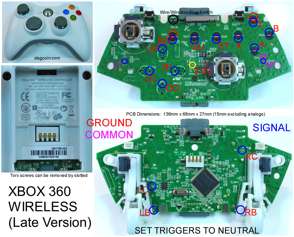
i tested out all my connection and found that the triggers don’t work. i thought i messed up some how but figured out they work with a different ground then the rest of the buttons.
it’s kind of hard to read what the letters say and there are a few different purples. there’s a more closeup picture out there but i’m not sure where it is.
Grrr! I’ve spent the last hour trying to solder to the normal points and I give up (the contact area is just too tiny, thinnest wire I have is 24AWG and my iron picks up the solder so I have nothing to attach the tinned wire to).
Does anyone happen to have a pic of the back alternate points scraped off/soldered to? I’m worried about accidentally scraping off a trace and ruining my pcb all together.