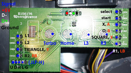
Does anyone have pics of the front and back of the HRAP3 PCB? I’ve looked around and found nothing. I want to mod my HRAP3 SA with an MC Cuthulu, Chimp, and MAdcatz retro stick PCB so it’ll work on pretty much anything. I want to keep the original Home buton functionality, so I’ll have to wire into the PCB since it doesn’t use a switched button. I need to know what the pin out on the bottom side is.
Honestly, you don’t really need the other side. I personally was able to attach a wire to the tiny contact points of both the Turbo and Home buttons there, and carefully feed them out through the small hole of the cover near the directional soldering points before screwing everything back into place. The rubber plungers for those buttons still work/activate them just fine, and you have the connection you need.
I don’t really have confidence in my soldering ability, that I’d be able to do the same and leave the button functional.
On another note. If I’m going to wire up the 360 and MC Cuthulu and use the push buttons for home. Will I also need to put power to the HRAP 3 PCB as well?
I use DPDT switches for dual-mods, so I might be wrong here: since you are going to be using an Imp, that will handle which board is transmitting data when you press any of the buttons, including Home/Guide. At any rate, voltage and ground have to be connected to the HRAP3 board in order for the Home button to work correctly. In this case, since you won’t be wiring up the D+/D- for the HRAP3’s USB to anything, you don’t have to worry about it doing anything other than activating the Home connection on your MC Cthulhu.
He is doing all that, but he still wants to use the Home button on the HRAP3 PCB. It took me a while to realize what he was asking too, don’t sweat it.