To my Great concern, there have been countless questions on “padhacking” and soldering and wiring in general. With brief knowledge about electronics, and a day’s worth of experience with an iron, wiring is by far the easiest part of building a custom stick definitly one of the most fun if you havn’t hacked 500 pads already. Anyways, this guide is intended to teach both HOW and WHY. Learning why will allow you to adapt your skills to any pad. This guide is divided into two parts, first, to determine where we solder to, and second, to how we actually solder to these places. How to Solder portion of this guide is currently incomplete cuz I’m lazy and half my post got deleted.
If you don’t feel like learning and you know where to solder to, you can just jump down to part 2.
Part 1. WHERE?!
What the heck is a PCB?
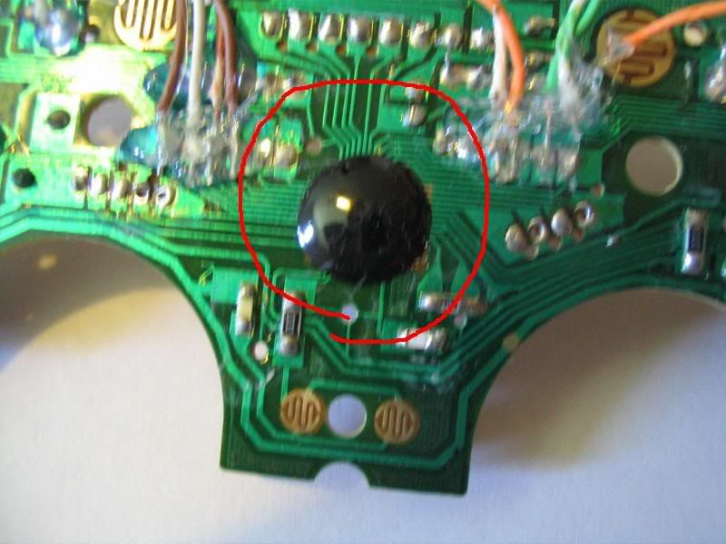
Good question. PCB stands for “Printed Circuit Board” which bassically means that green stiff board that is inside your controller with a bunch of weird things sticking out. The term PCB applies to any of these green crusty thingys (also known as epoxy board and breadboard) but whenever the term is used on srk, we usually mean the board inside your controller. The PCB inside your controller takes the button input you give it and translates that into something your computer can read. This translation process is known as encoding and the chip that does it can be referred to as an encoder. If you look hard, you will see several light green lines coming out of the encoder. Here isa photo, please keep in mind sometimes the encoder does not look like a black blob in the middle of a PCB. Bassically though, if it’s in the middle of the PCB and a lot of wires are going into it, it’s probably an encoder.

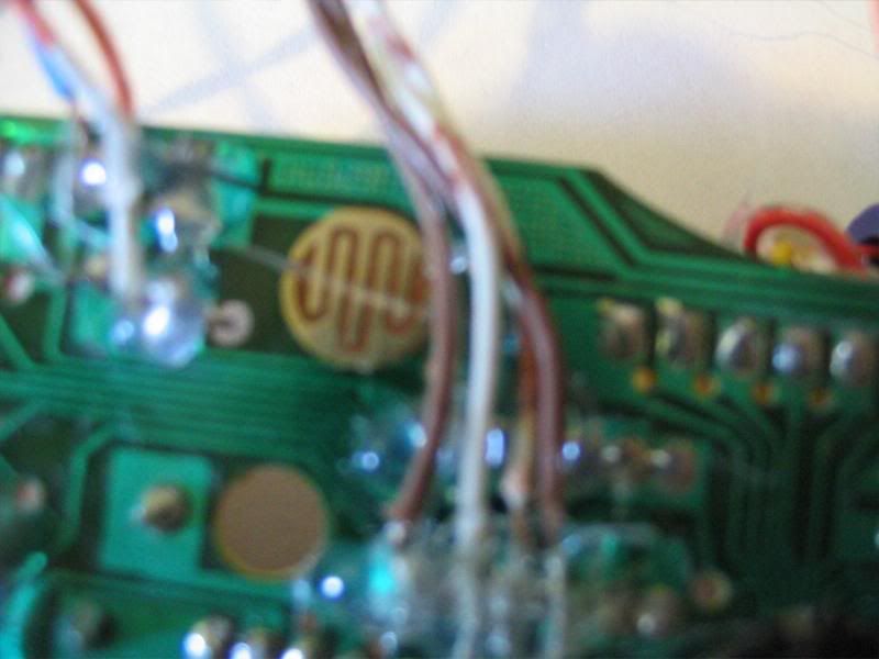
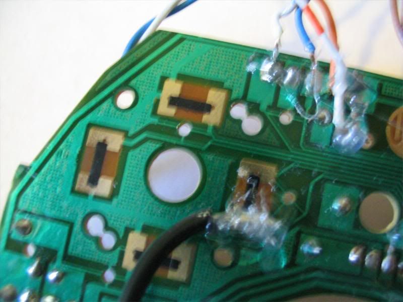
These lines are actually copper covered in a green enamel for insulation and will conduct electricity. (Yes! that means touching a screw driver to these lines WILL NOT blow up your controller, even when it’s on! BUt still not reccomended!) These copper covered things are commonly known as traces. If you follow the traces (also known as tracing!) you will notice that they lead to various funny looking things on your board, some may go through small looking squares or these circular shaped things that pop up on the PCB as well. The square and circle thingies that pop up on your PCB are resistors and capacitors, for all intents and purposes, you do not need to know what these are and what they do only that they are there ande you really shouldn’t remove them. A handful of the traces will go to the big fat wire that sticks out of your controller, once again, do not touch these ones. The traces that you DO want to bother with are the ones that lead to the button contacts. You can tell if it’s a button contact if it is right below the buttons. I took a picture of a couple different contacts (2) (which are actually from the same pad…) to show what they can look like. If you want, please check the padhackingthread on tech talk forum for more photos. Since it’s not in my pictures, I should quickly mention now that more often than not, these contact points are covered in this fugly black stuff that you can not solder to. You can either scrape this off or solder to a different point more on this later.


Moving on, as I mentioned there are oftentimes more than one point to which you can solder to. If you look carefully, you will find most PCBs to have these small copper dots on them. THese dots are referred to as solder points and can be… well… soldered to. http://i55.photobucket.com/albums/g140/chippermonky/Joysticks/wiring/IMG_8815.jpg
Now that I know WHAT a PCB is, HOW do they work?
Excellent question! If you havn’t guessed already, when you press the button down over the contact points that I was talking about it “shorts” out the two points that is to say it connects them. Remember how there are traces coming out of these two contact points that lead to the encoder? When you short out the two contacts, you are effectively shorting out two of the traces that are attached to encoder. The encoder chip is capable of detecting this short and when it does, it sends this info to your ultramodded xbox or whatever.
Since half of this post got F*ing deleted, You’ll have to live with my terse but still complete and comprehensible version of the rest.
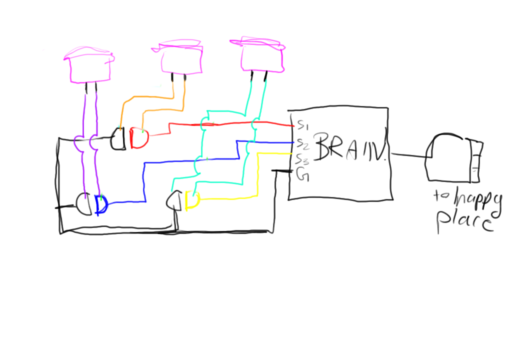
If you have a sharp eye, you might have noticed one of the two contacts of every button is actually interconnected! The side that is not interconnected is known as “signal” and the side that is interconnected is known as “ground” or “common”. Here is a simple picture to clarify.
http://s55.photobucket.com/albums/g140/chippermonky/Joysticks/wiring/?action=view¤t=bf3207d4.png&refPage=&imgAnch=imgAnch3
Brain is another way to say encoder, but if you use that word, people will laugh at you. s1 s2 s3 are signal1/2/3, there are more than one because you need more than one to detect more than 1 button! G stands for ground, duh.
Now since this is rather confusing for the first time, I’ll use an analogy to explain how “ground” works. Imagine you have 3 pipes with a viewing window in each of them. One end of the pipe leads to a giant water resevoir, the other goes behind a curtain. Behind the curtain, each pipe is connected to a valve and then all flow into a much larger pipe that leads back to the resevoir. This larger pipe is ground and the 3 smaller pipes are signal. When the valve for each respective pipe is turned on, you can see the flow of water through the pipe. In this manner, you can figure out which valves are on and off without being able to see the valves. This is the same principle on your PCB. The encoder is able to detect the flow of electrons through s1/s2/s3 but the electrons will only flow if they have somplace to flow to. When they are shorted to ground, the electrons are able to flow into ground and the encoder can detect this flow. In this manner, even though half the wires are interconnected, the encoder can still detect button presses.
So WHERE do I solder to?
Great question. Think about what your trying to do. You are trying to use your sexy sanwa/seimitsu/happs in place of the crappy plastic buttons on your controller. The plastic buttons, when pushed, short the two contacts so you want your sexy sanwa/seimitsu/happs to do the same thing. Looking at the bottom of the pushbutton, you will notice two connectors. When the button is pressed, these two connectors are short, and in effect, anything connected to these two connectors will ALSO be shorted. So if we connect the two contacts on the PCB to these two connectors, the two contacts will be shorted! Knowing that, you COULD simple wire up your controller like this:

However this method is excessive. Remember how one end of the contacts are common, that means one end of the pushbuttons are common as well. So we can actually connect all of one side of every pushbutton and then solder it to ground just once. THis method is known for some F*ing reason as daisy chaining. Here’s a picture to clarify:
http://s55.photobucket.com/albums/g140/chippermonky/Joysticks/wiring/?action=view¤t=wiring.png&refPage=&imgAnch=imgAnch8
Also, remember when I was talking about those solder points, the small round copper contacts that you can solder to? You can solder to these areas instead of the contact area that the cheap plastic button shorts like I’ve drawn in the picture and have been talking about. Bassically, imagine the picture I just linked to. If anywhere along the red wire there were a copper contact point, you could solder to this point instead of the cheap plastic button contact area.
I should quickly mention here about Sanwa and seimitsu joysticks. Some of them already “daisy chain” the grounds together so you will see only 5 connectors sticking out of them. One of them is ground and the other are signals. Just wire the ground to ground, and the signals to their respective signals. I don’t have a diagram to show which signal is which so if someone could kindly provide me with one, that would be nice.
I should mention 2 things real quick. First, some controllers for older consoles DO NOT have encoders. But it makes no difference, If for whatever reason you want to add a l33t joystick to your NES atari comodor or whatever (actually I think NESs use encoders and uhh, comodores use keyboards don’t they lol oh well) solder it the same way. Second, not all PCBs have a common ground, that is to say, they look something like this:
http://s55.photobucket.com/albums/g140/chippermonky/Joysticks/wiring/?action=view¤t=wiring2.jpg&refPage=&imgAnch=imgAnch1
in a case like this, just wire it up like I showed in my first picture:

On PCBs like these you CAN NOT use sanwa/seimitsus that use the fancy connector cables, because they already “daisy chain” the grounds together. You can use JLWs and some seimitsus however.
So I THINK that’s all I wanted to say about PCBs, but who knows cuz half my post got deleted :(.
**Part 2. It won’t stick! (soldering incomplete) **
So this section is incomplete and probably never will be. Having a guide on soldering is rather pointless, Just practice and you’ll get it! Read and take from it wat you can. You can always google for other soldering guys if you feel unconfident.
Now that you know exactly where you want to solder to, all that’s left is to solder. Good soldering requires two things, technique and practice. There are some things about solder that I simply can’t explain, after you have soldered a couple times, you will get the feel of how solder works and what is required for a good joint. Nevertheless, I’ll try my best to explain. You do not need much practice to solder well.
Tools
-Soldering iron, any iron with any tip will do, you are not doing very precise work here.
-Solder, prefferable rosin core and lead free. The Rosin is a type of “flux” that cleans the contact and help to stick. Lead free is for safety (duh). Do not get acid core, I believe those are used for plumbing…
-Desoldering iron/solder sucker/copper braid, you will inevitably make at least one bad joint that’s gonna get filled with impurities and you’ll find that no matter how much solder you use, you can’t get the wire to stick. These tools are used for cleaning up, one or all will do.
Understanding Solder
Solder behaves like nothing you’ve ever seen before and really to understand it, you must practice. Someone who has never seen the ocean before can not understand waves until he or she has seen it. Same case with solder. Play aroud with it and you’ll learn. But anyways, there are a couple things that really help to know beforehand. Solder is like a glue, do not think you are welding two pieces of metal together, what you are doing is you are glueing two pieces of metal together. In order for glue to work, it must STICK to what you are glueing. You’ll find much to your dismay that solder is not always cooperative and won’t stick. blablabal I finish later…
Final notes: All this is straight off the top of my head and everynow and then, I start believing something that is completely false to be true. So if you find some blatant mistake, please don’t be shy to point it out.
themes: Making jokes that aren’t funny. Thinking I’m funny when I’m not. Making drawing that look gay. Bitching about how half my post got deleted.

 It will probably cost you an extra few dollars but is better to use crimps as most of those buttons come with proper ends to crimp stuff to. Well, not that costly…you can probably buy hundreds of those crimp ends for a few dollars.
 )
)