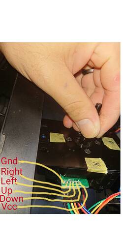
I’m thinking bout picking up the Hori Hayabusa Silent Optical Joystick. I hear it has a 6 pin harness and comes with a 6 pin cable. Is it possible to adapt this to my standard 5 pin harness while keeping my current cable stock?
I havent seen a te2+ pcb in person but normally what you would do is crimp a jst-xh female connector to the other end of the cable that comes with the hayabusa, for gnd, u, d l, r, and plug that in the connector on the pcb where the jlf cable was. Then find a place to solder the 6th wire for vcc. However ive read some posts that indicate the pcb might start acting weird if vcc is tapped.
Possible, you need to find a 5 pin connector to splice into your 6 pin harness and you also need to tap somewhere for VCC.
curious about this too, it says that one last pin needs to be soldered right into the PCB according to AS 
I have a silent hayabusa installed in my joystick. I’m using a brooks ufb so it’s pretty easy to install. The cable it came with is a six 6 pin harness on one side and no harness on the other. You could easily install a 5 pin harness on that side then manually solder the sixth wire. You’ll need to install a cable harness yourself if you want to use your existing connector.
Any one know if the VCC pin only provides 4.9 v if that will cause major issues? My Panthera only provides 4.9v when tapped into the VCC cable pin.
I’m sure it’ll do, there’s enough for more than just an optical joystick
does the non-silent optical have similar fittings?
Non silent hayabusa uses same connector as sanwa jlf
I just received my unit, it didn’t come with any type of instructions
can anyone tell me which end is the 5v?
on the stick pins, it says “1 CN3_2 6” with 1 seperated with a line.
The harness it came with has 1 being black and 6 being white.
Photobucket doesn’t host image visible to the public unless you pay them hundreds of bucks per year. Please edit your post, having uploaded your image on another hosting service. I use Imgur.
Thanks Jopamo, I think white one is 5v and black is ground,
I am trying to connect to Rasberry Pi, doesn’t seem to work with GPIO 5v pin for some reason.
When this stick works, the leds supposed to light up correct?
Thanks!
Self answer, even though I may be totally incorrect,
I did end up buying a 5v breadboard power supply which powered through a usb. Then, connected 5v from the supply to the stick! (whole 2 of them )
Works, for now >.<
Self answer, even though I may be totally incorrect,
I did end up buying a 5v breadboard power supply which powered through a usb. Then, connected 5v from the supply to the stick! (whole 2 of them )
Works, for now >.<
That is the way to do it, trying to power the Hayabusa via the Rasp Pi isnt a good idea.

