You do agree that having the LED controller completely separate from the Xbox pcb is a pretty definitive test about whether or not the LED controller works, right? And if the LED controller is defective like you believe, then you’d have to do this anyway when you replaced it, yes? Either way, we’ll know for sure. Just please have some faith that I may actually know what I’m talking about.
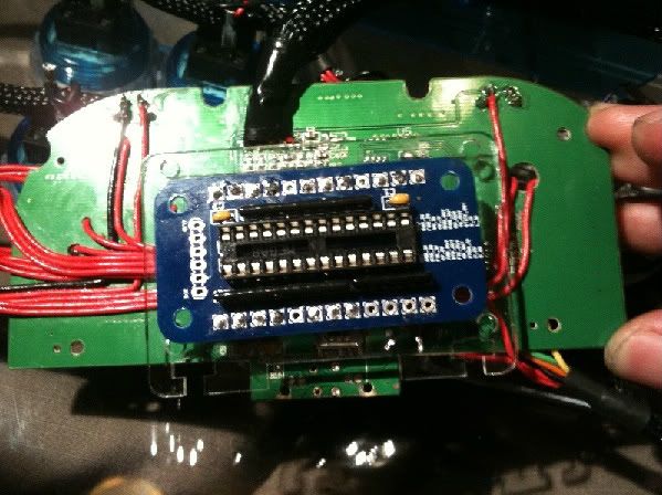
Ok, so to make as clear as possible through a picture, I hooked the board up to regular LED’s on my breadboard. This will make it easy to trace the wires by looking at the picture.
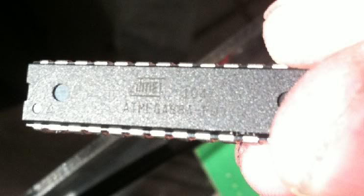
First I tested the LED’s and took a pic just to show they all work and they are pretty bright. (Note: the chip is a resistor array)
Next here is a picture of the wires I soldered. Vcc, gnd, the 6 outputs, and jumpers between jab,strong,fierce and ground.
I took a few pics from different angles before powering on to show what was hooked up to what.
Now I hook it up to the board put power to it and I get the same result as I’ve been getting. All LED’s on but very very dim. Its tough to see in the picture but I took a couple with and without flash to attempt to show it.
Lastly I disconnect the ground wire connecting jab,stong,fierce to ground. This has no effect on the LED’s
Well that’s pretty messed up, thanks for doing that. Last thing, can you check the voltage on pin 1 of the chip? You can leave the black probe where it is, Im just wondering about that one pin.
The boards simple so the most likely problem could be an unprogrammed chip, but that wouldn’t really explain the dimness in the LEDs. Either way, I’ll double check the chip in the kit before I send it out.
Label’s just been printed; I personally programmed two chips; one to go with the replacement kit and the other as a spare in case you want to salvage the board you’ve been using here. I dont think it’ll make today’s mail pickup, so expect it to go out on Saturday.
Didn’t realize that this post was so recent when I started researching a problem I’m also having with the FGWidget LED controller. I’ve triple and quadruple checked my wiring and used two separate kits as well as checked a third chip from another kit but I keep getting all LEDs glowing dimly unless I disconnect ground from the controller board. When I do that, it acts as a pass through to the LEDs and they turn off when pressed.
The setup I’m installing into is a MadCatz TE stick with a Kitty TE board installed and checked for proper function.
The wiring is as such: Kitty TE installed as per instructions, Signal IN for each button on the LED controller is going to the Signal connectors on the barrier strip in the TE stick. Signal OUT is going to the GND label on each KNsert in the same order as the Signal INs. Ground for each KNsert is fed to Ground on the barrier strip in the TE stick and checks out with my multimeter to ground on the controller board.
I’ve been pulling my hair out over this install, first the artwork I ordered for my client was delayed by a week or so since it was printed too large the first time but then I ran into this and I’m just frustrated about this job. Also, since I ordered 11 kits, are they all likely to have an issue? I’m saying this under the assumption that I have the same problem as Maxito which isn’t necessarily the case. Should I remove the chips from each kit and try them out individually or is there a way to check them with a multimeter? I’ve had good experiences with your other products and just want to know if I’m messing something up. Thanks!
It’s very possible a mistake was made flashing the chips. Im putting together a little test rig together to find out right now. Im going to go ahead and send out a box with three replacement chips to you to make sure they get out in Saturday’s mail, and over the weekend I’ll have the test rig setup so I can check the rest of my stocked kits and also test the reprogrammed/replacement chips. If it looks like the batch is all bad, I’ll get the rest of the replacement chips out to you in Monday’s mail.
Thank you so much, I’m going to put something together as well so I can show people at the store how the boards work as well. It may just end up being a rental stick with a piano hinge or something so I can get inside and swap out chips for testing though I may consider a different socket for multiple removals and insertions. Thanks again!
Okay, first the important news; the test rig was put together, and first thing I did was test out a chip identical to the replacements I just send y’all in the mail. Same chip, same code, hand programmed by me, worked peachy. So Im confident that the replacement chips that are en route work properly.
I’ll be spending time tonight and tomorrow to check over the batch currently in my kits. If it looks like a widespread problem, I’ll start going through my orders for the past few weeks and start sending out replacement chips.
Okay, it does look like there is a problem with the chips in this batch. If Im understanding this right, it stems from using the wrong fuse settings on the 88A chips I had, when the usual LED controller is a 48. So yes, this one’s totally on me. I’ve ordered a big batch of the usual chips that should arrive Wednesday; I’ll go through, program them, and send out replacements to recent purchasers. If anyone is in dire straights and need a replacement chip ASAFP, please let me know; I’ve got about 3 of the correct chip here that I can program, test, and ship out asap, otherwise they’ll go out on Wednesday or Thursday. Feel free to dismastle, dispose, or repurpose the current busted chip however you may like.
I agree. Joe just ordered some and he’ll definitely need replacements as well. Can you handle waiting until Wednesday/Thursday for your replacements to go out, or do you need some asap?
Toodles, I ordered my FGWidget January 10th. I just finished putting together my joystick tonight and I am experiencing the same LED issues. I understand replacements will be ready by Weds or Thurs. Will you be mailing the replacements to everyone who ordered a widget within a certain date or do I need to contact you about this with more specific details for a replacement?
Well, that’s good confirmation for the 10th or before, so Im thinking I’ll just send replacement chips to any US orders that ordered in January and international order on or after Jan 10th. The international orders pre-Jan 10th I’ll send an email, because shipping those just freaking nails me in the pocket book, and I’d like to get confirmation before I spend $18 each sending a $2 part.
To answer more directly, there’s no need for you to send a PM or email; everyone I send replacements to should receive another paypal notice about a shipping label being created. If you don’t see one of those emails by late Friday, feel free to email or PM to be sure.
Also, I’m wondering if you can give me your help in tracking down a short circuit issue I’m having. I’m using the FGWidget with 6 buttons and joystick. I am having an issue with the up and down com circuits being shorted out. I’m pretty sure the short circuit isn’t related to the LEDs always being on thing.
Chippy
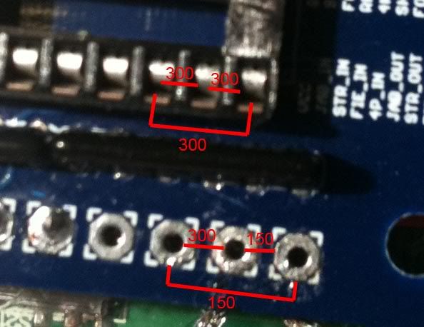
I have tracked the short circuit down to something on the FGWidget board. I believe I may have a faulty 6pin resistor array. The FGW has a short between Xtra_IO, U_IO, and D_IO. However, there is resistance in the short circuits. In ohms
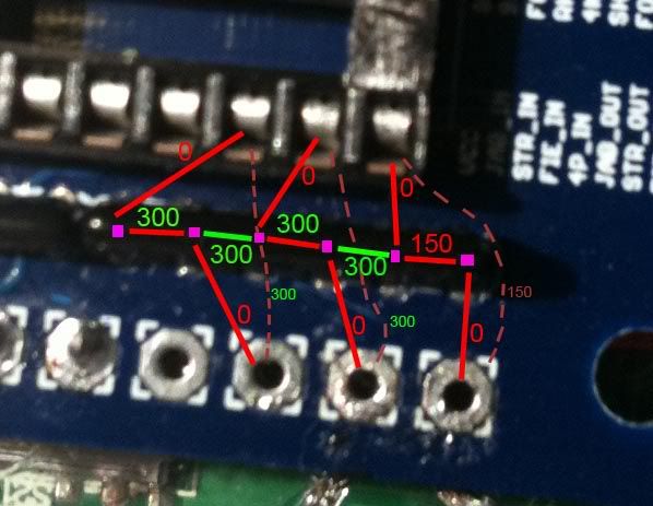
This is the resistor array pin resistance measurements going from pin to pin. In the following picture lines and text in red are what I assume to be normal. The green lines and text are assumed to be out of the ordinary. The dashed lines denote the reading from the chip leg socket to the hole
I am assuming that if I had shorted something out with wire or solder the short circuits would have a resistance of 0 ohms instead of 300 or 150 ohms. I’m really trying to avoid having to pull the FGW install apart off since I just spent so long putting it together on my first super wiring attempt.