Help soldering directional pad connections xbox 360 controller

Hey yall,

This is my first time building a stick :smiley: Everything has been going OK so far until I got to this point where I have to solder the directional pads…

I am really having a problem getting a wire soldered to those funky small little spaces. Even with tinning the wire, I can not get that spot to be tinned (or pre soldered or whatever).

So I tried a plan B, but it doesn’t seem to work, and I am hoping you guys can help me understand why…

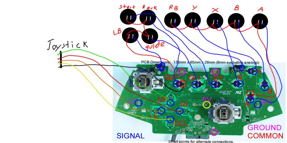
Here is a diagram of the PCB I am working with:

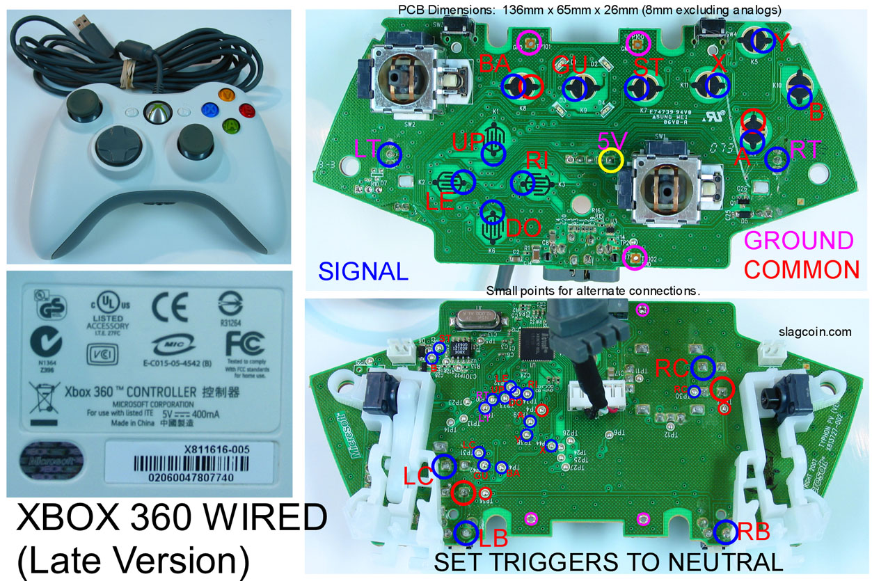
So here is what I tried: I tried to use the spot on the bottom of the PCB (it’s the bottom diagram in the image), and solder a wire to the spot that says UP. I managed to do this with no problem at all. I then plugged the controller in and touched this wire to a ground wire… and nothing happens…

With my other buttons I have done so far, when I touch their signal wires to their matching ground, it acts as if the button was pressed.

Did I scrape too hard or something on the other side and wreck my PCB? (And Is that why everyone says be careful using those ones?)

Or do I need to use a specific ground for this one? I used a generic ground… If I Need to use a specific one… which one?

Thanks for taking the time to read!

EDIT:

Also just FYI the main question I have is why this does not work as I expect it to. I thought that if I touched the signal to a ground it should “close the circuit”, is this correct? If so why does it not work in this case?

I think I am misunderstanding something about that diagram or something, but I am not sure. I found this thread:

http://forums.shoryuken.com/showthread.php?p=5455032

but it does not answer my question as I am using the spot that is suggested I just don’t know what to do with it after that… X_X

With those directional solder points, you just have to be patient. It sometimes takes a while to get a good joint on em.

I did actually use the pink one… So I need to use the red?

Can you explain why O: ? I thought all ground was the same but obviously not X_X

The red spots are the common ground on the official 360 wired common ground controller slag coin diagram. Hence it saying “COMMON” on the key. All signals must in some way have a connection to one of these (Whether that be by daisy chaining or not).

You may have to be patient when wiring up the D-pad signals (I did anyway, terrible soldering job) but just test everytime you attempt to make a connection then retry if it doesnt seem to work, you’ll get there in the end.

EDIT: Heres a diagram CoverlessTech created that helped me understand before I began work on my common ground stick.

As I understand the diagram you posted COMMON does not equal GROUND in this case. The controller is built in a way that the buttons labeled in red share the common connections marked in red - but that does not necessarily mean that common equals ground electrically. So to say it is not really a “common ground” controller (where ground would really be common for all buttons) but a controller that shares a common reference potential for most of its buttons (all except for LT and RT as it looks).

Put simply because the triggers are analogue they use a different ground connection from the non-analogue buttons. The two grounds for the triggers run back to the same place so you can use either of them for the LT & RT ground.

This following may only apply to the MS 360 Wireless Late Version pad…

Slagcoin’s diagram is a little hard to understand from just the image if you’re a first timer like us. He expects you to glue the variable resistor (the knob that turns for each analogue trigger) to the position it’s in when the triggers are released.

There is another method lots of other folks use where the analogue trigger components are de-soldered from the pad. This requires soldering a resistor in it’s place. I can’t remember the thread but there was a great explanation for this (search thread title: “XB 360 triggers” on the forum, as I remember).

As for the direction buttons, soldering to those tiny pads is for lunatics. I recommend a far simpler method. Follow the traces from the tiny pads back to a little hole. This hole is called a via (wikipedia it). Open them up with a scalpel and you can poke a thin wire right through the circuit board. So easy to solder, so much stronger, you will laugh that you even tried the other method. I promise, or your money back. Diagram: http://s99.photobucket.com/albums/l314/Beartron/?action=view&current=P2058914a.jpg <- photo is of the Wireless version pad. Wired version looks like it has quite different connections.

He/She did but it wasn’t working because the wrong ground was being used.

That diagram is awesomely helpful…

The only thing it’s missing is the triggers, but I think degauss’ explanation will suffice for getting those working. (I am going to leave my triggers on, and use their signal and a ground to a button… that should work right… :slight_smile: ? )

Anyways, everyone thank you for your posts. I am in the work room now testing to see if I just needed to use the common instead of the pink ground.

Thanks degauss for pointing that out!

I read all the replies and thanks everyone for reading and replying,

I will let you guys know how it goes!

Ok that was the problem. Thanks a bunch you guys I learned a lot from this thread!

I scraped away at the vias until i got the copper contact exposed but when testing, i don’t get a connection while touching a ground to the exposed via. Sticking in a super thin wire gets no connection either unless i shimmy the wire in random directions resulting in intermittent connections. how did you manage to clean the inside holes of the vias?

Your not supposed to clean out the hole if its filled in. They’re filled with a conductant that connects the trace from the top of the pcb to the bottom.

Just Wanted To Add Since Not Alot Of People Know,
There Is Another Method For Soldering The Analogue Inputs For The Triggers.

Not Gonna Go Into The Tech Side Of Things With An Explanaition Of Why This Works Cos I’m Goin Out In A Sec But If You Leave The Trigger Solder Points In Then Its Really Easy.

1st Look At Your Slag Coin Image And You’ll See The Two Signals For The Triggers Circled ( The Middle Blob Of The 3)
Then Solder Your 2 Siggnal Wires To Those Two Points
Now All Thats Left Is The Common, Well They Dont Have One; Simple Solution: Use The Ground Of Your PCB (Any Pink Circle) Exactly As You Would Use A Common And You Hav A Digital Representation Of Your Analogue Triggers.

I Know This Might Not Be That Descriptive I Did It Today But Didnt Take A Picture So Feel Free To Ask Any Questions
Peace