Help please... USB Controller PCB

I was able to buy a USB controller and already dismantled it, although I just wanted to request some assistance in diagram on what to wire and where the grounds are.
here i’ve mapped where the buttons go (already tried it with my ps3 and the controller mapping is a mess):

here’s one without any markings:

If anyone can help me please, I’m afraid to make a mistake then ruin my system with just a controller thanks

Looks like it may not actually be a common ground controller. All the buttons (aside from perhaps Turbo) look fine (you can see that they each have one side that touches/connects to the “fill” of the ground plane, the large green grid that covers most of the board) – those are grounds, and are all electrically identical. However, the D-Pad is a different issue – my best guess is they’ve got a single control line shared on each axis, and then it either gets pulled high or low. You can see that left/right share a signal line, because there’s a large trace between the two of them, but while left connects this signal to ground (what you’d expect), right connects it to another line coming from the pot’d circuit. I suspect if you had a multimeter, that would read +5V or +3.3V, but it doesn’t really matter – the long and the short is that this thing is not entirely CG.

If you’re just building a scratch stick/controller from this, not planning on doing a dual-mod with another PCB, this won’t be a big deal, but you’ll need to wire to both sides of each of the directionals (or, at least, the “high” and “common” lines for each, if they share a common on up/down as well). These would then go to the switches on your joystick, after some PCB modification to split up the default commonly-wired ground signal. There’s a guide to that in one of the stickies, IIRC. Good luck!

EDIT: OH, and remember to not connect both the left and right or up and down non-common lines at once – there should be a resistor in there, but it looks like cheap Chinese-made junk so there’s no telling for sure. And don’t connect them together, either.

thank you very much. i’ll check on this and i’ll post any update.

underwing is exactly right. I did this for you to make it easy.

you need to check DC voltages with the controller connected and check resistance with the controller disconnected. that will tell you all you need to know for the D-pad. you might not even need to know where the resistors are. you really only need to sort out what is V+ on the UP of your D-pad. in the picture you can see I guessed it like that thinking that y would be common just like x is common to x.

thank you. this is really helpful. so in layman’s term the d-pad shares 1 ground but the other buttons have their own grounds that can be use right?

http://interactive.usc.edu/membersmedia/npashenkov/voltage_divider.jpg

so if (V+ = 5v) and (R1 = R2) then Vout would be 2.5v

since 5V*(1/(1+1)) = 5V*1/2 = 2.5V

so for example, your controller always has half of your V+ at the place marked X in the picture. when you press left. it jumpers both sides of R2. this makes Vout = 0v since the path to ground is now a wire. it works in a similar way when you press right and Vout = V+. with the black probe on ground, use multimeter to test the voltage at both sides of the UP button. the one that reads the higher voltage is your V+ pad. your V+ for UP and RIGHT is already connected on the board so you should have no problem with one V+ wire to both UP and RIGHT microswitches. you can daisy chain the ground for LEFT and DOWN with your buttons. the X common gets daisy chained to LEFT and RIGHT. the Y common gets daisy chained to UP and DOWN.

just for fun, you can test your D-pad for resistance with the controller off. it probably has a 1k resistor in each direction.

Not… quite. First of all, a “second ground” is a misnomer – a second “common” is the more appropriate term (as there can be only one ground, because that effectively means a connection to +0V, connected to the black wire from USB).

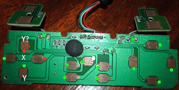
Also, thanks to tigermaskchi for bringing in the proper circuitry, and doing teh shoop diagram, for great knowledge! For clarity, the green dots mark the ground pads on each button – however, I’m not sure that we can trust the TURBO/AUTO button markings, as their common line doesn’t connect to a known ground. If you’re not using these buttons, it’s no big deal, but just keep that in mind.

Speaking practically, when you wire the other (non TURBO/AUTO) buttons, you’ll need to tap into one ground to use as a common, and then the unmarked pads on each as the signal wires for each button. Connecting those signal wires to the ground wire will effectively “press” the button, so you can daisy chain off the single ground wire. This should also work for left and down signals, as those need to be shorted to ground to be activated.

Right and up, however, you’ll need to run a wire from both pads directly to both terminals on the switch of the joystick – if you’re using a JLF, this means cutting the common ground trace with a dremel between each switch, and wiring each pair to the now-isolated switch terminals on the PCB. Because you cut the terminals, of course, you’ll also have to bring ground to the down/left buttons individually, but they can be daisy chained instead of brought through via separate wires.

As for shoulder (L/R) buttons, the small solder joints on either side of the green dots in tigermaskchi’s diagram are going to be your signal wires – you can just wire them and figure out which is which later, or you can try to visually follow which line goes to which button (or even better, just use a multimeter). Feel free to remove/discard the short 3-signal ribbon cables, and the small daughterboards with the actual contacts on them, as they’ll serve no purpose.

on the UP and RIGHT, V+ is marked in RED although the UP V+ is just my best guess since I can’t test it myself. you can share V+ on UP and RIGHT but if you dont have a way to find V+ for sure with a voltmeter then you could run dedicated wires for UP to the two terminals of the UP microswitch. you don’t need to cut any traces if you buy a JLF-TM-8T. the JLF-TM-8YT has a PCB with common ground already wired so you should not buy that if you can avoid it.

my brother will be helping me with this. hopefully it’ll be a success. thanks for your help guys :slight_smile:

i’ll post updates.

woohoo all wired up!
tested the up and right dpad and it works!

wired and with QDs :smiley: buttons and box are the only things left.
connections already tested and working :smiley:

still waiting for my buttons from akihabarashop.jp and currently it’s still pending. i just want to clarify one thing cause i’ll be buying a drill bit later for making the holes.

when i make a hole for the ff should it be:
24mm buttons = 24mm drill bit
33mm buttons = 30mm drill bit

please give some insight :slight_smile:

30 mm buttons = 30 mm drill bit. Typical Japanese buttons are 30mm.

24mm = 15/16 in
30mm = 1 3/16 in

the cad drawing of the 30mm sanwa OBSF-30 shows a 30mm body but when you put the button in, it gets tight because of the 4 ribs on the side. you can carefully cut the ribs off or you can enlarge your 30mm hole to 30.5mm. test fit them first and don’t make the holes too big. a good install takes time.

thanks for the replies :slight_smile: still trying to find a way for the 24mm holes. i could get it done by a shop near my place but wanted to do it on my own first

step bits or fostner bits. I prefer step bits on metal but anything works on wood. plexi can crack so its good to use a sharp bit and lay it totally flat with good support. you can’t find 24mm or 30mm bits in america but you can go on amazon uk or ebay uk.

already done with the box. just need to paint it and put holes :smiley: no news from the buttons from akihabarashop.jp though.

http://slagcoin.com/joystick/layout.html

:slight_smile: Should help you layout your buttons!

I’d print out a layout to proper scale (double check it post print), then tap it down so that you can just drill straight through it.

thanks actually i had the site bookmarked cause it helped me a lot.

i’ve got a little dilemma, how thick should a wood panel be for me to use snap in buttons? i wasn’t thinking ahead and bought snap in rather than screw in sanwa buttons. geez.