Help from some of you electronics gurus (Hot Tub hardware hacking)

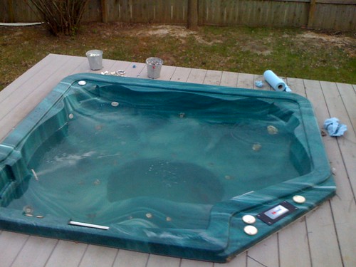
Okay, so after years of futzing, I’ve finally gotten my hot tub running (from spare parts and a used tub shell). :slight_smile:

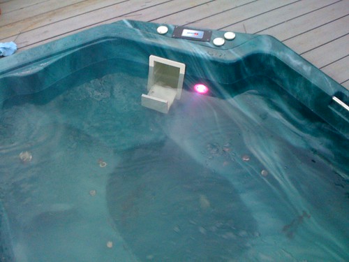
So here’s where I need help - that control panel above, what is called “topside controller” - It’s for a Gecko (Spa Builders) S-Series controller, model K-18. I want to read that output and be able to track it from my computer. It’s three segmented led displays, like this:

http://www.thelearningpit.com/lp/doc/7seg/7seg.html

My question is this: is there any easy way to accomplish this? If I’m reading correctly, there are 8 pins on each led - ground + A-G. I could run a weatherproof cat5 cable out to the topside, and there is an IC in it, coated in silicon goo. It’s probably an LED controller, if I recall there were 5 wires running to it. Extra credit would be to read the 5 status LED’s at the top, and extra double-plus credit would be to allow me to send the button presses for the 4 microswiches (that last one really is one button - press it once and hold, the temperature starts cycling up, press again, it cycles down). The reason for this is that I’m paranoid about the whole thing freezing up this winter, and would like to have access to the topside controller.

Please note, if you can tell me how to read the state for each segment, I can sort it out in code to charaters. I know perl, this isn’t hard. I can simply make a hash like this:


my $led = {
	a => 0,
	b => 0,
	c => 0,
	d => 0,
	e => 0,
	f => 0,
	g => 0,
};


The ones that are on I’d simply change to a 1, then I could convert my hash to a character, for example the letter “F” would be this:


my $led = {
	a => 1,
	b => 0,
	c => 0,
	d => 0,
	e => 1,
	f => 1,
	g => 1,
};


The number “8” would be all 1’s, “A” is the same, only d => 0. You get the idea. Any ideas on how I can do this?

Looks like I have 2 steps I need to fulfill (jump in any time guys…)

  1. I need to get ahold of a MAX232, which will convert RS-232 serial to 0 and 5 Volts.

  2. I need to identify the IC in the topside controller.

At the most basic level, and the peak of inefficiency, I could just run an RS232, tie it to a single LED on the receive and ground pins, and be able to tell the state of that one LED at any given time - I think…? So that gives me (literally) binary communication - with one freaking bulb. :stuck_out_tongue:

I’m going to need some help with this one guys, sorry. :slight_smile: I’m thinking I need something that polls the state of, oh geez - let’s do some math here, 7 pins x 3 positions, so that gives me 21 + plus the 5 LED’s at the top indicating jets on/of, blower on/off, temperature program, filter cycle, and heater on/off - giving me a grand total of 26 states that I need to track. This is starting to sound more and more like some sort of weird pad hack the more I think about it - and then we start talking about those pushbuttons - which I guess would be me doing the same in reverse - I send 1 of 4 states on the receive lines, the last button being the trickiest, because I would need to see real-time feedback from the led’s, as the temperature goes up or down based on holding down that last button. Would be cool if I could send a numeric value directly, but I’m trying to keep this simple! :slight_smile:

BTW - here is where I’m doing my reading up on how to read stuff off of a serial port. The plan is to use weatherproof cat5, and one of those nifty cat5->db9 adapters (if I can find one…)

http://www.beyondlogic.org/serial/serial3.htm

Alright, I’ve had some time to think about this - I think I have a grasp on what I need to do, barring that I’m able to decipher the pinout of the IC on the topside.

There are 26 led’s I want to watch. Presuming that I’m not going to mess with trying to do handshaking or anything fancy like that, I could do 7 data bits, 1 stop bit - maybe 9600 baud? So I make a small circuit that does kind of a “strobe” across all of the leads, polling for states, and simply sends them back, the first led would be byte 1, second byte 2, third byte 3, then the 5 top led’s would be byte 4, leaving 2 bits unused. Maybe then I use those 2 blank bits to somehow signal the start of a new polling cycle? Anyway - the thing I don’t know how to do is check which lines are pulled high, which ones are low, and then feed that info the to RX lines on the MAX 232. Once I understand that - then maybe I can work on sending binary values for those 4 switches, and send an open/close on those switches to actually control the thing?

It’s an 8-wire molex, not a 5 wire. My mistake…

Left to right on the molex:

black
brown
red
orange
yellow
green
blue
white

I’ll try figuring out what the IC is when I get home. The manufacturer doesn’t even know! :stuck_out_tongue:

This is certainly curious - what are the odds that this thing is already RS-232???

http://www.ecst.csuchico.edu/~dranch/HARDWARE/common-cables.html#references


Signal  	Function  	 	 	Adapter   	RJ-45
------- 	--------- 	 	 	--------- 	-------
CTS 	 	Clear To Send 	 	 	Blue  	 	1
DCD 	 	Data Carrier Detect 	 	Orange 	 	2
RD 	 	Received Data 	 	 	Black 	 	3
SG  		Signal Ground 	 	 	Red 	 	4
SG 	 	Signal Ground 	 	 	Green 	 	5
TD 	 	Transmitted Data 	 	Yellow 	 	6
DTR 	 	Data Terminal Ready 	 	Brown 	 	7
RTS  		Request To Send 	 	White 	 	8


I’m not holding my breath, but if there’s a MAX-232 in there, and I find a clock crystal, i can calculate the baud rate based on the value of the crystal (if I can make out the value of the crystal…), and I’d be in business, just have to work out how the data is sent to and from the board. :slight_smile:

Alright - I got home and popped open the topside. I found the 8 pin molex, what looks like a crystal (a little metal cylinder) labelled C1, with the following printed on it:

F3
10
16V

I also found a 20 pin IC, with the following printed on it:

MC14489BDWE (Found this one - datasheet: http://www.freescale.com/files/timing_interconnect_access/doc/inactive/MC14489B.pdf )
K60A2
XAA0536

The only marking on the side of the 3x7 segment display was:
WGA038691-34

It looks like page 6 of the IC tells me that this is in fact not just an LED controller, but it expects serial data, AND it has a serial out. If someone can confirm I’m not going crazy, doesn’t that then mean I should be able to grab data off the data out pins and passively read what’s being sent to the topside controller?

I’m sitting here trying to decide something. Do I need to somehow wire data out from the Motorola chip into a Max232, then run that to my computer, or if it’s already serial data, just hook data out and ground directly to the Rx pin and ground on my serial port? If that’s the case, this is going to be a dead simple hack so far as getting exactly the data the topside is getting. Deciphering it all might be messy, but getting the data might not be too bad at all. Also so far as I can tell, there should only be three of the 8 wires hooked to the Motorola chip - Enable, Data In, and Rx? That leaves 5 wires running in unused, which doesn’t seem quite right to me. There has to be more to this.

Pin 14 - is “signal ground”, and pin 18 is “data out”, or in my mind, the tub’s “Tx”.

So here’s what I’m thinking - I have a nice little RJ54->DB9 adapter sitting here. It has pins 2 (Tx), 3 (Rx), and 5 (Signal Ground) hooked up, and nothing else. I’m thinking I modify this thing so that pins 1 (Carrier Detect), 4 (Data Terminal Ready), and 6 (Data Send Ready) are tied together, and pins 7 (Request to Send) and 8 (Clear to Send) also should be tied together. That should sufficiently trick my serial port into thinking all is well with the serial connection, then I’ll run pin 18 on the motorola chip to pin 3 on my DB9 adapter, and pin 14 on the motorola chip to pin 5 on the DB9. With any amount of luck, that should give me the bitstream that the control unit for the spa is sending to the topside controller. I hope!

Really - you guys can chime in here any time. I’m in WAAAAAAY over my head here! Heeeeelp!

What you were describing doing at first would have been really complicated. But, knowing what chip that is, it actually become a but doable.

First thing: That chip does use serial, but it uses Synchronous (clocked) serial. The max232 is for Asynchronous (unclocked) serial. It’s just not going to help.

The next pieces of information you need are pretty much going to require an oscillicope. You need to know the frequency of the clock line, and also how often commands are sent/received. After that, you’re going to want to figure out how the buttons are sent back out of that chip by watching the output line.

But, if that chip you linked the datasheet of is the one controlling the good stuff in that panel, what you’re wanting became a whole lot easier to do.

Right now I’m separating this out into two tasks:

  1. Simply read the log the status of the topside. Which lights are on?
  2. Be able to send button presses.

If that’s the case, looking at post #11, does that sound right? It’s clocked serial, but then so is the serial connection on my side - I think? If I’m trying to accomplish that first goal, just getting the bitstream should be enough, and I can sort it out in software. Of course, I still need to know the baud rate, which drops us right back to needing to know what the clock crystal is, and the reason you say I need an oscilloscope, which I don’t own. :frowning:

So far as whether or not the motorola chip is controlling all of the “good” stuff on the panel, I don’t know. I see nothing in the chip’s documentation that mentions anything about transmitting commands from button presses. That makes me think that there is a second IC buried in that thing someplace - or if only 3 wires are being using to control the LED’s, that leaves 5 wires - and 4 buttons. Perfectly plausible then to have those buttons mapping back to the mainboard of the spa master controller under the deck.

That looks like a relaxing hot tub…
You have my full support in your endeavors!

Maaan, would I ever be upset if I bought a hot tub only to set it up at home and discover that it’s a stressful one! :bgrin:

Looking at Numbski’s progress, I’d say that is one stressful hot tub.

You won’t be able to hook the Motorola chip up to a PC serial port. PC serial ports are Asyncronous; they use a set baud rate to control how fast the data line changes for each bit, and some framing bits, so the communication can work without a clock line. That Motorola communicates over a syncronous serial connection. It has a clock line, so there is no real worry about the transmission speed or any framing; when the clock line drops, the bits are read. When the clock line goes up, the bits change. Forget about the max232; what it does is entirely different. The max232 takes the transmit and receive lines from a PC Serial port, and converts the line levels. PC serial shows a 0 bit as about -12volts, and bit 1 as +12 volts. Most microcontrollers and other DC electronics devices don’t have any sort of negative power, and if they have asyncronous serial support, its usually 0v-5v. The max232 makes a pretty easy drop in to converter those 0-5v chip signals so they’ll work on a PC. Great tool, but irrelevant to what you need. I don’t know of any way to directly convert synchronous (clocked) serial to asynchronous(PC serial).

I has asking about the frequency on the clock line because if the frequency was moderately slow, you could hook it up to a parallel port, and let your software rapidly read the state of the not_ENABLE, CLOCK, and DATA_IN lines on the motorola chip.

Another option would be an Arduino. It can read that clocked serial stuff just fine. Uses an FTDI chip so it shows up as a USB serial port on every damn OS known to man including BSD’s. Uber open source and programmable so you should be able to easily code it to do anything.

If the buttons are connected to other wires on the molex, then reading or writing them would be easy. I checked the datasheet, and it doesn’t appear like it can do anything with the buttons, so I think you’re right that they go through other wires.

Well, when Numbski’s done with this stressful hot tub, he can just plop in and relax =)

OT
Hopefully I’ll understand this stuff in a few years.

This tub has been stressful beyond belief. It’s a shame my blog is down, I’ve been working on building it for almost 6 years! I actually have plans for building it using a storage tank, and cutting off the top. You could build it that way, and heat it using a charcoal pit or fireplace, and build the whole thing for under $200, presuming you were okay with tons of chemicals and changing the water VERY frequently. :slight_smile: Self-contained filter unit runs about $100, and an ozonator will cost about $75, and worth every penny - add $25 for a Nature2, and now you’re at $400. Instead of the storage tank, I found a used hot tub for $300 that had a dead control unit. So now we’re at $600. The big expense is that I opted to refurbish the control unit - which was $900, and as I went electric rather than solar, the wiring ran me $700.

If someone wanted to go 100% solar, they could probably do it for under $1000, but not use it during the winter. Next spring I’m thinking of adding the solar element back into the plan, both with solar cells, and a solar water heater tank on the roof. Should reduce energy consumption down to nearly zero during the warm months. Winter is where I’m paranoid. I want to be able to use this thing year-round, which is why I want to track the water temperature over time, and heck, if I can interface serially to the master control unit and control it all via a serial cable - added bonus. :slight_smile: Would be nice to be able to set a cron job so that midnight the tub drops off to 80 degrees, and maybe at 3:30 pm it cranks up to 105 degrees - minimizing energy use.

The nice thing is that the docs on the Motorola chip tell you straight up what bits are for what characters on the serial interface, so even before I get it wired up properly, I should be able to write a simple Perl module that takes the bitstream and converts it to characters.

Well, let’s talk about parallel for a moment - it has a very limited distance under which you can work if I recall - something like 30 feet? I might be okay doing it that way, but I’d be lying if I said it didn’t concern me. I think I see where you’re going on that though. If I know what frequency to read the parallel port, I can try to sync up my reads to the frequency of the clock crystal. So - is it possible for me to simply locate the clock crystal and determine it’s value by looking at it, or do I really need an oscope to measure it?

As for the Arduino - I’d looked at that, but was concerned about the cost, weatherproofing it, and the allowable length of the run for USB (presuming I had to put the device outside). If I can put the device inside and simply run a cat5 between the topside and the Arduino, then that might be a viable solution…