I had the honor of going through my electronic guru RDC to fix to broken happ spillproof buttons. The hex converter was fried along with the sensors. Most of been reversed wired at some point and blew that magic smoke. Anyway heres a little something on how these buttons work.
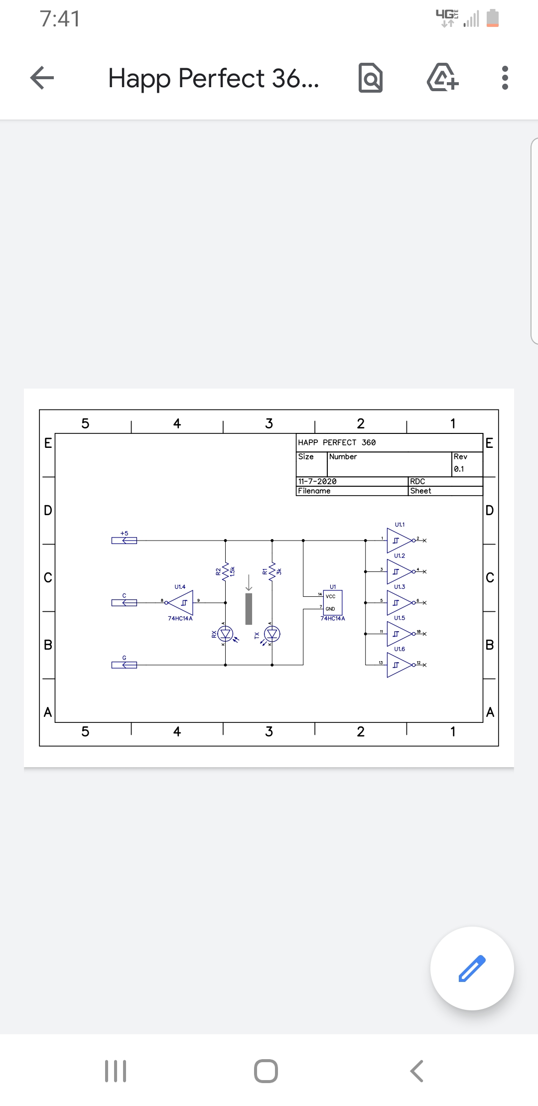
TX is the PhotoDiode
RX is the PhotoTransistor
U1 is a Hex Inverting Buffer, it just has 6 of the same thing in it, only 1 of the 6 is used.
R1 is the current limiting Resistor for the PhotoDiode so it doesn’t burn up.
R2 is a PullUp for the Input of U1p9
U1 is an Inverting Buffer, so what gets put into it gets inverted on the Output. So you put 5v in, you get 0v out, you put 0v in you get 5v out. There’s no middle ground there or negative voltages or anything, just 5v or 0v (ground).
The other 5 Inputs of U1 are all tied to 5v to keep them in a known state. If Inputs are left to float, that is not connected to anything, weirdo things can happen.
The TX and RX just make up a switch pretty much. The TX is an Infrared Diode, and when that IR light hits the RX Diode it makes it conduct.
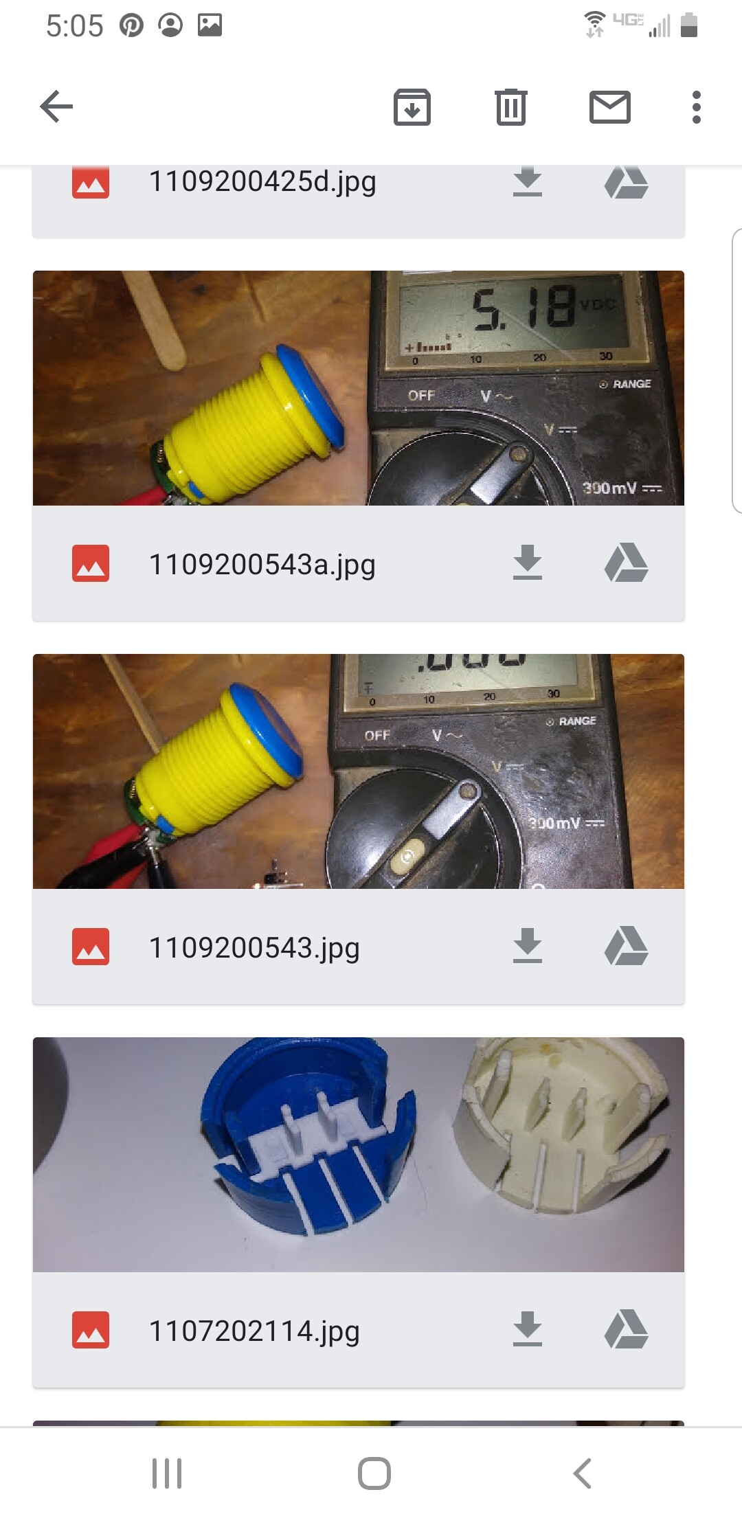
With the button in an unpressed state, TX shines on RX, so it conducts and ground will get to the input of U1p9, and 0v at the Input of the Inverter means there is 5v on the Output.
With the button pressed, it blocks off that beam of light and RX stops conducting, so R2 pulls the Input of U1p9 up to 5v, and 5v on the Input means there is 0v on the Output then.
My work log from RDC: OK, they both done, and will work down to 3.3v if you wanted to use them on something that ran that logic level. like an XB1 controller. Just remember they are an active Lo type of switch, so the drive the button line to Ground when pressed.
+5 goes to 5v, or 3.3v source.
C goes to the button line, ie; A or X or whatever.
G goes to Ground
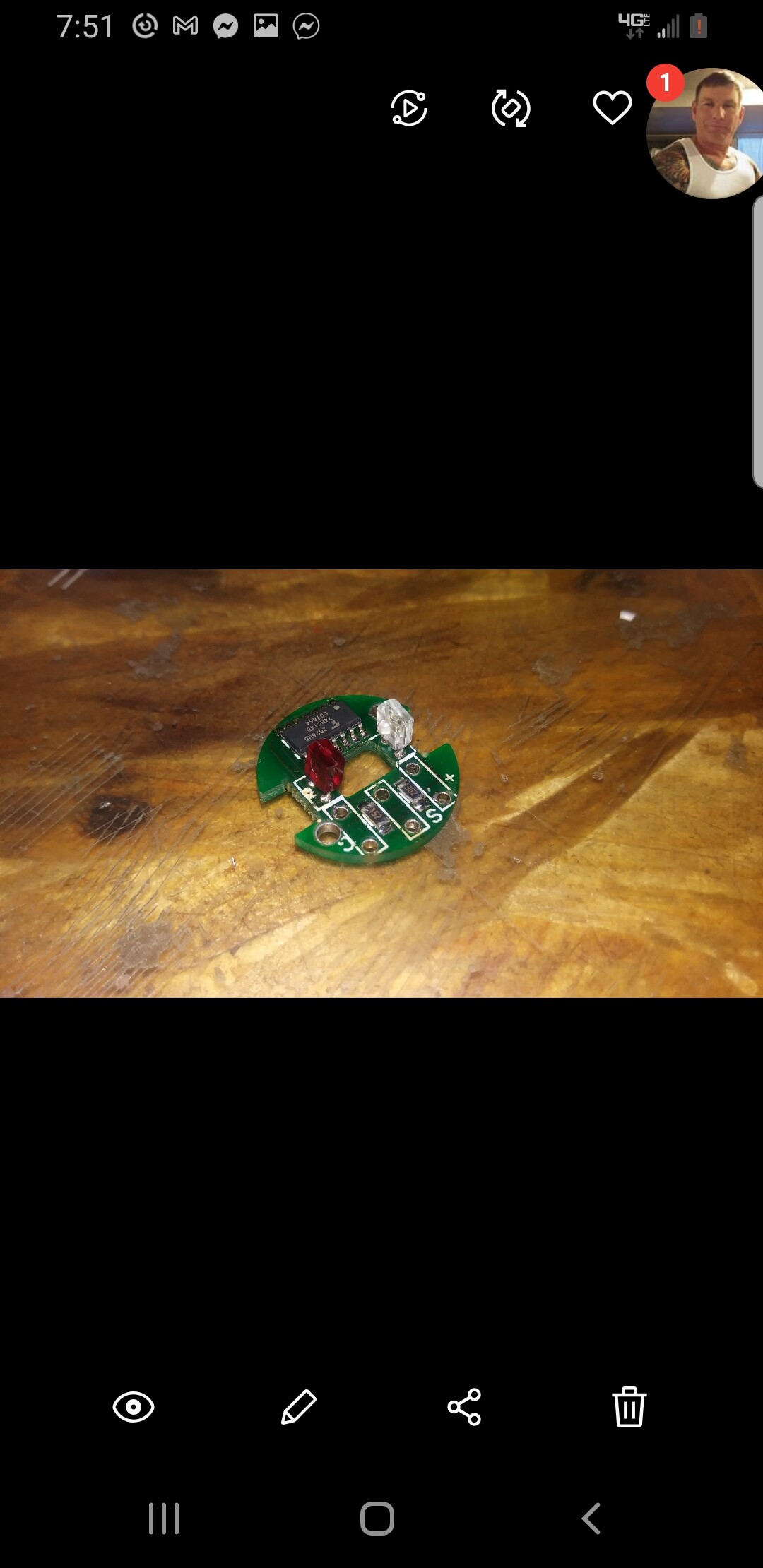
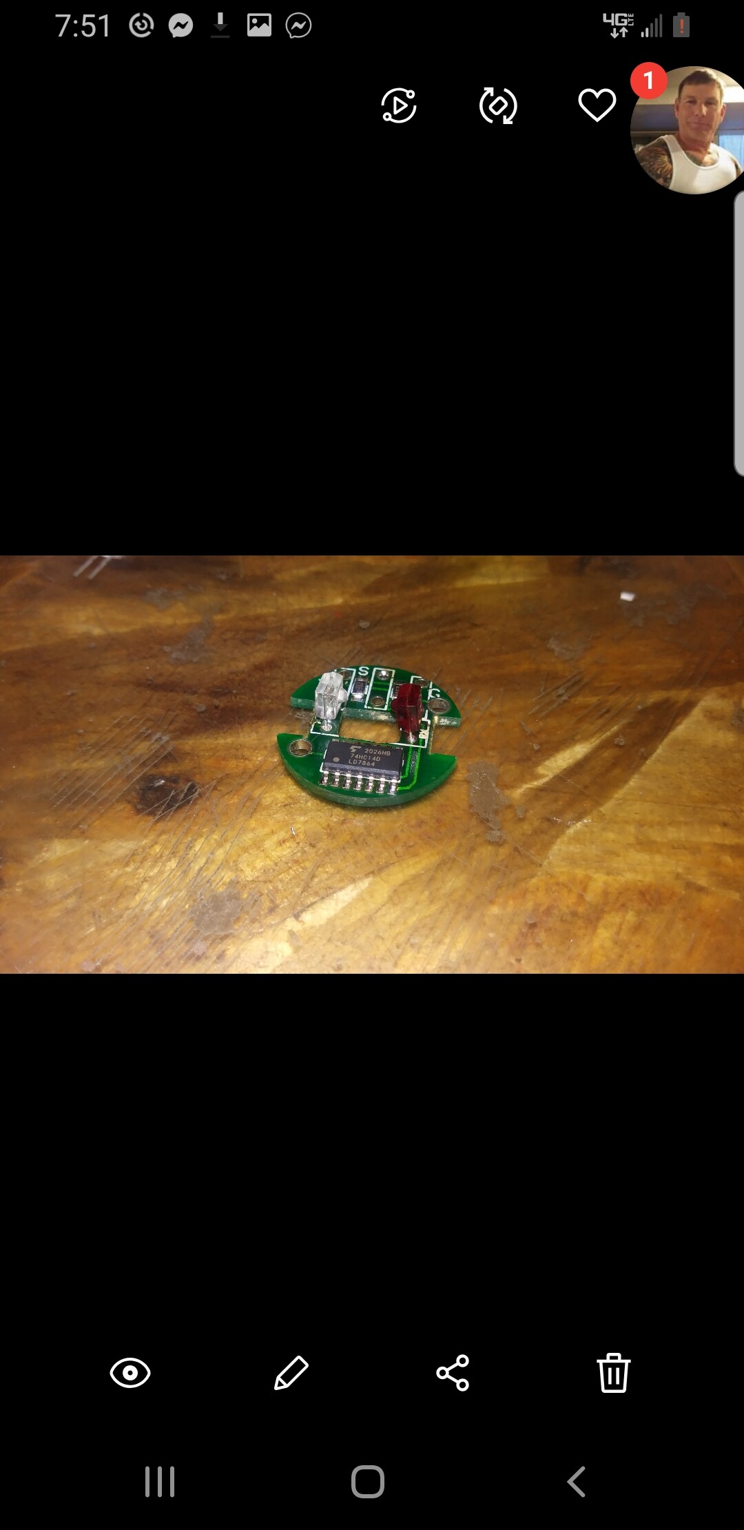
Almost everything in them is new now, as I just replaced the PhotoTransistors (Receivers) as well being they are matched to the new PhotoDiodes (Transmitters) that needed replaced. They most likely would have still worked every bit as well with the old ones in there, but really no point in doing it half arsed when the new sensors had them right there to use anyway. They are basically a couple of new photo-interrupters now, which is really all they were to begin with, just made from components from who knows where.
Not a whole lot to see in the pics, and the 3k Resistor in there was changed to a 470 to drive the new PhotoDiode better.
RDC diagnosis when received my buttons:
OK, I’ve gone thru these and they must have been wired up backwards at some point or have just given up some of their magic smoke over time.
Short version, cost you around $40 for me to go thru them and replace what needs done to get them going. Long version, read on…
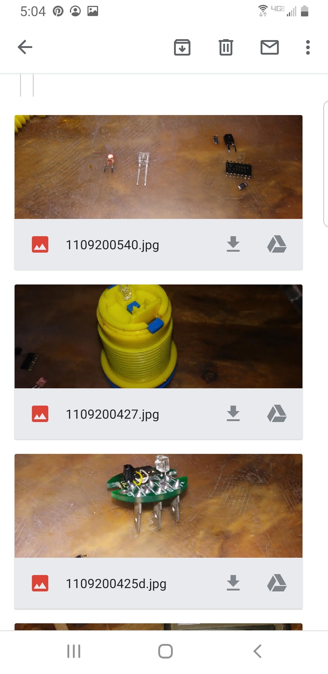
It’s not any kind of really complicated circuit in there, just an IR Diode, Photodiode and Hex Buffer Inverter, then a current limiting Resistor for the IR and Pull-Up Resistor for the buffer input.
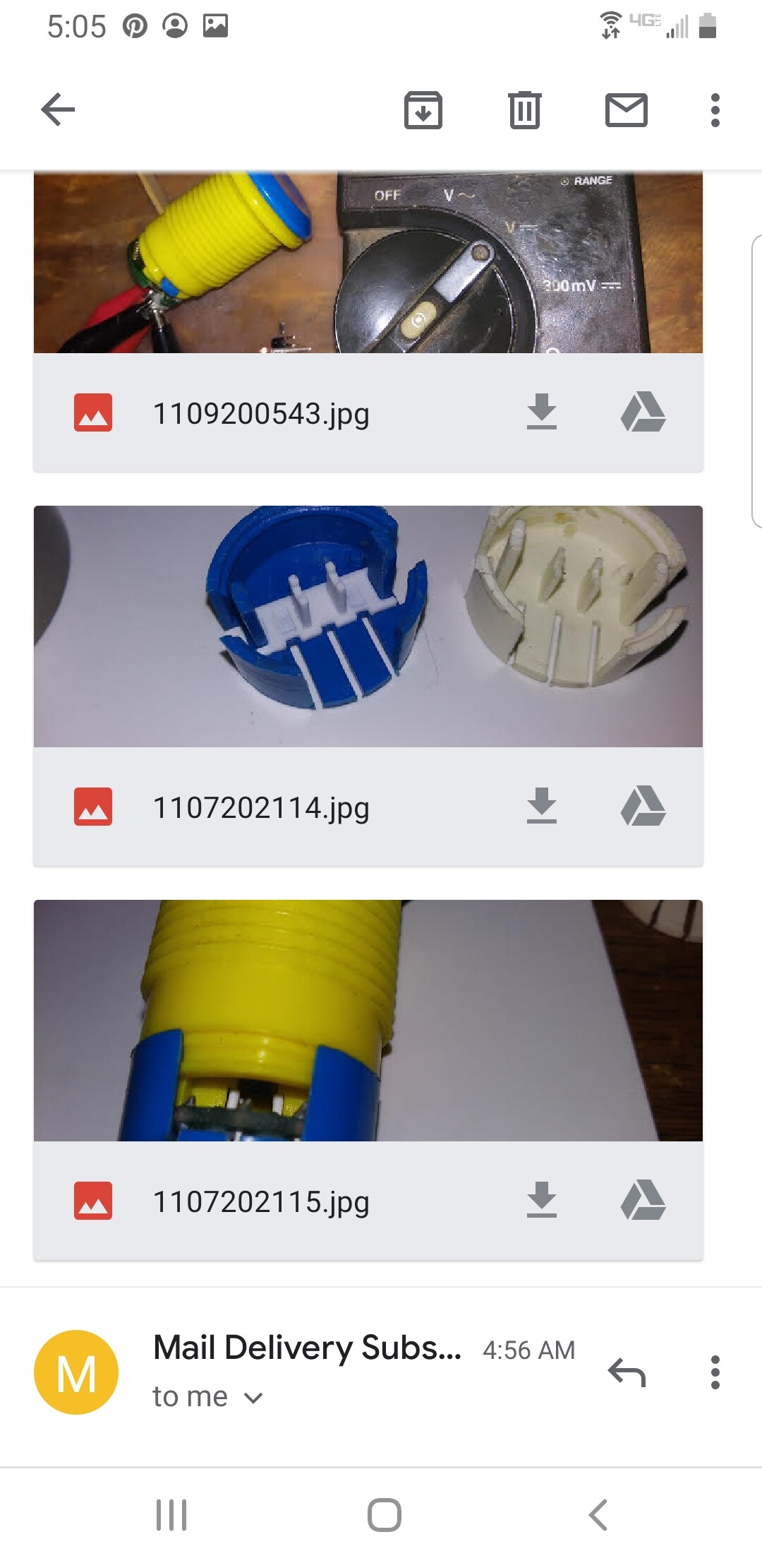
I pulled everything off of the one to schematic it out, don’t freak out there, nothing was damaged in that process, aside from the stuff that already was bad and it will all go back together again.
So the IR LED and Hex Inverter are bad. The kind of kick in the shorts are there’s no way to really cross those particular IR diodes.I looked thru a pile of them and everything is quite a bit larger physically. The original one in there is 3mm wide and 4mm tall, and pretty much everything out there now is 4.6mm wide. That normally wouldn’t be too big of a deal, but the thing has to fit into the bottom of the button housing there, and there is about 4mm at most width wise there.
I got to thinking a bit and tore open a SX4088 I had here, and the IR in it was 4mm wide and it just fits in the housing. Tested that out, rewired the hex inverter to get on a good part of it, since it has 6 of those circuits in that one chip, and she came back to life.
So what they both need is a new IR Diode and I’d replace the hex inverter versus rewiring it to a good section of it. Then some 3D printing to replace those broken shields in there on the blue one.
RDC
Thought I’d share the tech side to what’s inside of these things. For their age they are very durable. I found it interesting, hopefully so did everyone else.