Dual Shock 4 PadHack Thread - aka you should padhack the hfc4 pad instead

UPDATE: Just padhack a hori fighting commander 4 instead.

So you want to add PS4 functionality to your arcade stick? Well too bad. Just wait until there is a third party pcb that is cheap and easy to wire up. Maybe we’ll get lucky and there will be a firmware update to any of the
custom ps3 pcb’s that are out in the market. Oh, you don’t want to wait? You really want it now? Well the only option right now is to padhack a Dual Shock 4 controller. Luckily for us the pcb is common ground. Unluckily for us
the pcb is a pain in the ass to wire up and is quite unforgiving if you mess up. You thought the Xbox One pad hack was hard? This pad hack shits all over it. You accidentally burn off or rip off a contact pad on the ds4 and
you’ve just wasted $60. The only option after that is to find a via that traces to the contact pad that you’ve just destroyed. They are not easy to find nor solder to.

So if you think you have the skills or are looking for a challenge you have been warned. Don’t hold me responsible if you damage your DS4.

With that being said, let the padhack begin! We will start out with preparing the ds4 pcb.

To begin opening up the DS4 you must unscrew the four screws on the back of the pad.
http://i79.photobucket.com/albums/j138/gocontourgo/projects/DS4_Padhack/IMG_0336_zps442ab332.jpg

You’ll need to use a size #0, #00, or #000 Phillips head screwdriver. If you don’t own one then I suggest buying a Husky precision screwdriver set.
http://i79.photobucket.com/albums/j138/gocontourgo/projects/DS4_Padhack/IMG_0337_zps65fe8af9.jpg

You’ll need to use a little force to pull apart the shell, but don’t pull the shells too far apart too fast. There is a ribbon cable connecting the usb jack to the ds4 pcb. Pull the ribbon cable out first. Then unplug the

lithium ion battery pack. Then cut off the rumble motor wires.
http://i79.photobucket.com/albums/j138/gocontourgo/projects/DS4_Padhack/IMG_0338_zps823d7882.jpg

Circled is one more screw that holds the pcb to the shell.
http://i79.photobucket.com/albums/j138/gocontourgo/projects/DS4_Padhack/IMG_0339_zpsced0a56e.jpg

Be careful as you lift the pcb out. There is still one more ribbon cable left that needs to be unplugged. It might be a bit difficult to unplug with your finger so using tweezers or forceps will make things easier.
http://i79.photobucket.com/albums/j138/gocontourgo/projects/DS4_Padhack/IMG_0340_zpsde1f7a4d.jpg

If you have very tight space limitations inside your case you’ll probably will want to desolder the analog jacks and neutralize the axis with 10k ohm resistors. However, for most applications just cutting the stubs and gluing
the stick in place will suffice.
http://i79.photobucket.com/albums/j138/gocontourgo/projects/DS4_Padhack/IMG_0341_zpsb1f0d7c5.jpg

If you want to use the micro usb jack, and I suggest you do, then you’ll need to unscrew four screws that hold it in place. The top two have to be removed first. Then the led light thingy can be removed to gain access to the
bottom two screws.
http://i79.photobucket.com/albums/j138/gocontourgo/projects/DS4_Padhack/IMG_0342_zps8f1dea6e.jpg

Remove and set aside the micro usb jack.
http://i79.photobucket.com/albums/j138/gocontourgo/projects/DS4_Padhack/IMG_0343_zpsf0d6dec8.jpg

This is where you’ll be wiring up the joystick and buttons to. Looks fun doesn’t it?
http://i79.photobucket.com/albums/j138/gocontourgo/projects/DS4_Padhack/IMG_0345_zps3e268abe.jpg

To gain access to the copper contact pads the carbon residue has to be scraped off.
http://i79.photobucket.com/albums/j138/gocontourgo/projects/DS4_Padhack/IMG_0346_zpse7c0faea.jpg

I have a pick set that I got from radio shack that I use to scrape off the carbon pads. The one on the left I accidentally broke in half from trying to pry something off. I suggest not using these picks to pry stuff off.
http://i79.photobucket.com/albums/j138/gocontourgo/projects/DS4_Padhack/IMG_0348_zpsb592d658.jpg

Here’s the pinout for the 18 contact pads and which need to be scraped. It is the same for all the model revisions 001, 011, and 020.
1-(Don’t worry about me)
2-L1 (needs inverting)
3-10k ohm to pad4
4-L2
5-right
6-up
7-left
8-down
9-ground (Don’t worry about scraping me either)
10-home
11-x
12-circle
13-triangle
14-square
15-(Don’t worry about me too)
16-R1 (needs inverting)
17-10k ohm to pad18
18-R2
http://i79.photobucket.com/albums/j138/gocontourgo/projects/DS4_Padhack/IMG_0349_zps2f5337b0.jpg

Tin the contact pads. Use flux as necessary.
http://i79.photobucket.com/albums/j138/gocontourgo/projects/DS4_Padhack/IMG_0350_zps46ac45f6.jpg

Tin the two very small contact spots in the rectangle for Select.
http://i79.photobucket.com/albums/j138/gocontourgo/projects/DS4_Padhack/IMG_0351_zps5e8432e9.jpg

Tin the two very small contact spots in the rectangle for Start.
http://i79.photobucket.com/albums/j138/gocontourgo/projects/DS4_Padhack/IMG_0352_zps4cd67d9f.jpg

Look at this. This is the ribbon connector for the usb jack. See how simple this is? Want to see how hard your life will be if you don’t use this? Just check out the next picture.
http://i79.photobucket.com/albums/j138/gocontourgo/projects/DS4_Padhack/IMG_0354_zps133a474f.jpg

These are the four pins you will have to solder to if you don’t want to use the micro usb jack. Pretty small and cramped there.
Note this pin out is for the JDM-001 model and the pictures will reference to that model.
8- Vcc
10- D-
12- D+
14- GND

Pin out for the 011 and 020:
7- Vcc
8- Vcc
9- Gnd
10- D-
11- D+
12- Gnd

http://i79.photobucket.com/albums/j138/gocontourgo/projects/DS4_Padhack/IMG_0353_zpsdb05b9bc.jpg

Of coarse removing the ribbon connector will make soldering to the contact pads much easier. This route might be necessary if you are limited in case space. In which case you’d have to remove the battery jack too.
http://i79.photobucket.com/albums/j138/gocontourgo/projects/DS4_Padhack/IMG_0355_zps79565b7c.jpg

Now the DS4 pcb is all prepared to begin the wiring!

I strongly recommend using thin wires like 30 gauge wire. I get mine from radio shack: http://www.radioshack.com/product/index.jsp?productId=2062641
You’ll also going to want to make sure your wire stripper can handle the tiny sized gauge.

http://i79.photobucket.com/albums/j138/gocontourgo/projects/DS4_Padhack/IMG_0357_zps21e06c8e.jpg

If you are planning to wire up the usb and not use the jack then you’ll want start there.
http://i79.photobucket.com/albums/j138/gocontourgo/projects/DS4_Padhack/IMG_0359_zps3bbdb835.jpg

Make sure the wires are long. Would be a good idea to hot glue the wires to the board to keep them in place.
http://i79.photobucket.com/albums/j138/gocontourgo/projects/DS4_Padhack/IMG_0362_zps135af94a.jpg
http://i79.photobucket.com/albums/j138/gocontourgo/projects/DS4_Padhack/IMG_0363_zps7b54f109.jpg

If you are able to, go ahead and mount the DS4 pcb. It will make figuring out how long you’ll need to make your wires a lot easier.
http://i79.photobucket.com/albums/j138/gocontourgo/projects/DS4_Padhack/IMG_0364_zpse85d0a27.jpg

Shown here is wiring up the Ground wire. Since the Xbox One pcb was the closest I wired up the ground wire to a ground contact spot on the xb1 pad.
http://i79.photobucket.com/albums/j138/gocontourgo/projects/DS4_Padhack/IMG_0365_zps61abf629.jpg

The closest spot to wire up the 5v was on the PS360+.
http://i79.photobucket.com/albums/j138/gocontourgo/projects/DS4_Padhack/IMG_0367_zps1e3242d2.jpg

The data lines went off to meet the physical switch. In this setup, I’m using a 4PDT switch that has a off in the middle position. Two poles are for the usb data lines and a third pole is for the home signal. With this setup I can make the home button work for All the systems without having it accidentally turn on either ps4 and/or xb1 wirelessly.
http://i79.photobucket.com/albums/j138/gocontourgo/projects/DS4_Padhack/IMG_0368_zps8f142d9d.jpg

Now begins wire up all the buttons. I begin with the joystick’s right direction. The xb1 pcb’s joystick signals spots are the closest so I wire the ds4 there. I try to make the wire as short as needed and to glue down the wire along the way.
http://i79.photobucket.com/albums/j138/gocontourgo/projects/DS4_Padhack/IMG_0369_zpsdd0c32f9.jpg

All four directions wired up.
http://i79.photobucket.com/albums/j138/gocontourgo/projects/DS4_Padhack/IMG_0382_zpsa87b7cf1.jpg

A close up of Start and Select (respectively). The terminal strip is pretty close, but I decided to continue wiring up to the xb1 pcb.
http://i79.photobucket.com/albums/j138/gocontourgo/projects/DS4_Padhack/IMG_0384_zps4aa10eb7.jpg
http://i79.photobucket.com/albums/j138/gocontourgo/projects/DS4_Padhack/IMG_0385_zps28e476f3.jpg

Here are the 10k ohm resistors wired up for pads 3+4 and 17+18.
http://i79.photobucket.com/albums/j138/gocontourgo/projects/DS4_Padhack/IMG_0386_zps78ce37c3.jpg

L1/R1 inversion:

Since the L1/R1 buttons are active high we will need to invert them tomake them active low.

This is what the dead bug circuit using transistors and resistors looks like to invert the L1/R1 signals.

https://lh3.googleusercontent.com/-rO4onvShBcw/VM2b09ztFiI/AAAAAAAAAhQ/KASDDBzh-Hc/w256-h195-no/trinvert.gif

And not of much help, but the circuit wired up and glued to the bottom of the case.
http://i79.photobucket.com/albums/j138/gocontourgo/projects/DS4_Padhack/IMG_0391_zps33e7a992.jpg

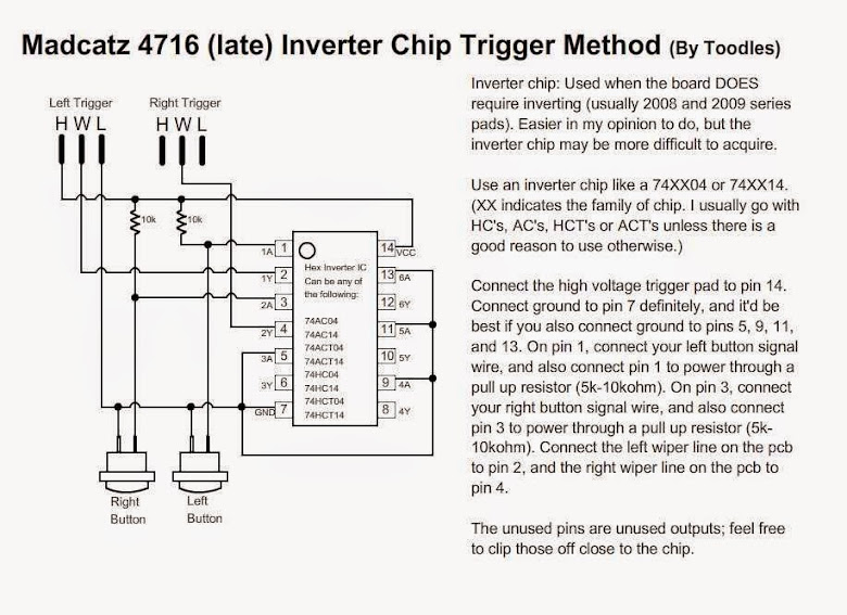
Or We can reuse the same method that was used on the madcatz 360 pads that also had active high triggers. Note that in Toodle’s schematic he used the A/Y pair 1 and 2. I will be using pair 1 and 6 to make wire routing easier.

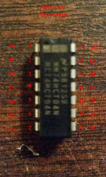
I’m using the 74HCT04N chip. Pins are labeled.

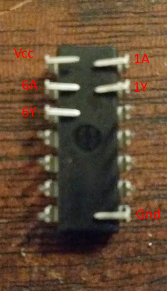
I’ll be using the dead-bug setup. Since its on its back all the pins will be flipped. It is important to remember this.
6A: To L1 button
6Y: To ds4 L1 signal
1A: To R1 button
1Y: To ds4 R1 signal

Here is an example of the 10k ohm resistors soldered to the pins.

Here is an example of 10k ohm SMD resistors soldered instead.

That should be all the important stuff for wiring up the DS4 PCB. How you want to wire up the usb is not in the scope of this post. Maybe I’ll use the third post for things like that nature and other FAQs.

reserved for…idk yet. maybe dremel.

please please please dont use crappy radioshack wire for this. I suggest 26 or smaller for contacts that small

LOL at the topic name and LOL for the JDM written on the silkscreen (james working for Sony now ?)

Thank you gummo for putting your expertise in a task like this

That’s actually solder you are looking at, not wires.

Radioshack makes some decent 2630AWG, speaking of wire.

I’d recommend using a fiberglass pencil for cleaning the contacts. They pop up at the odd Radioshack, or they can be found online fairly cheap. They’re abrasive enough to scrape off soldermask and that carbon stuff, but not abrasive enough to hurt the pads or traces.

Hmmm…fuck that.

I’ll be using and recommending 30 gauge wire : radioshack.com/product/index.jsp?productId=2062641&filterName=Brand&filterValue=RadioShack
Since its so thin it lowers the risk of the wire pulling off the contact pad. Plus start and select will have a very small contact area to solder to.

no what i meant was anyone who does this dont use the radioshack 22ga wire.

Gummo I never even knew radioshack had 30ga. is it online only because the radioshacks i have been to only have the crap wire

Edit:
Also gummo, are those contact pads closer than the contact pads on the snes pad
http://i189.photobucket.com/albums/z234/phreak97/snescons/uscon.jpg
I am of course speaking of underneath the chip

They carry them in stores too. I got the exact same (down to the color) ones at my local one. They had 3 colors. The next wire up was 24

I’ve got a few spools of that wire from RadioShack (used it on my dual wireless mod a while back). Find a striping tool, trust me. Also, be careful that those wires are securedm as they will break easily if you’re not careful

Actually I had pad hacked a SNES pad before attempting to duplicate one of Gummo’s projects, they aren’t that bad.

Other than the L1 and R1 needing inverting I think I could handle this. I never attempted Inverting before.

Also, I think I am project Boxing this PCB when i get my hands on it.

That’s awesome guys I never knew that radioshack had anything other than the red, green, and black crappy 22ga wire which is why I always say stay away because that wire will pull up a contact pad in a heartbeat. Ill have to try some of their 30ga even tho I still prefer my Fry’s 26 or 28 as I find 30 to be really brittle.

Yea I have padhacked 6 without problem and that included removing the chip. The contact pads on the ds4 don’t seem to be be closer than on the snes especially being offset like that, so I just wanted a reference of how close they actually are.

I will probably do the same and throw it in a project box when actual games come out for it that I want to play. I may also make a portable stick that is trimodded with ds4, xb1, and xb360 pcbs. That should give me all 4 systems if the ds4 works on ps3 as well and is not screwy in dual mods, otherwise I will just stick with project boxes.

Because they are offset the side by side space is actually further spread apart than the snes. I would still remain very cautious when wiring up the ds4 as you really don’t want to damage the contact pad.

The spacing for the usb connecter is smaller though.

Yea that USB space looks extremely tight.

Why do L1 and R1 need inverting though?
Could you invert them with a 74 chip or do you use another method?
Also does the ds4 act nicely in dual mods?

L1 and R1 are active high unlike the other buttons which are active low. In theory you should be able to use a hex inverter, but out of 3 different versions I had on hand only 1 worked. I’ll prob attempt it again some time, but for the mean time I’ve just been using transistors to invert it. I’ll be posting the schematic for it in the wiring post section.

The ds4 behaves fine in dual mods. Ive already done a few ps4/xb1 mods.

That’s disappointing, as I really like the ease of the 74 chips.

I also actually meant more along the lines of why does the pad invert them in the first place, like what is the point for just those two buttons.

Also does the ds4 work flawlessly on ps3 or are their special circumstances that you may have observed where it does not.

My guess is because of the space limitations for the traces on the button ribbon sheet. There’s no way for the ground trace to reach the L1/R1 buttons because of the traces for the L2/R2 buttons block the way. So the triggers have to share a trace which is a voltage source.

The only downside of using the ds4 on ps3 is that the home button does not work. It registers as a button press on PC though.

Thats interesting thanks, I am always interested in how pcbs are laid out.

Disappointed about the ds4 not giving you a home button on ps3. That may be the kicker that makes me go full project box with my sticks in the near future.

Looking forward to your wiring diagrams and pics of trimods/quadmods that are sure to follow.