Dual modding 101

Introduction

This guide is aimed to give newbies a full understanding of the workings of PCBs in controllers and arcade joysticks, the process of the dual mod, and shouldn’t be considered a simple “Step 1, do X, step 2, do Y.” I highly recommend you grasp an understanding beyond “Connect this to that, etc.” If you are willing to take the time to read and understand farther beyond a step-by-step process, not only will you find the process easier, but you will also be able to troubleshoot more effectively, and in turn, be a much better modder than someone who only understands it as a process. This also doesn’t intend to be a simple guide for dual modding X model stick from Y system to work now on Y and Z system, which certainly stretches the length out as well.

While most of this information is already out there, I aimed to make this a more “complete” guide, which will not only work for one case of a dual mod, but will work for many more cases, and will be in simpler, more explained terms than many other guides out there.

I haven’t found a guide quite as complete as I’ve attempted to make this one, and I’ve tried to make it a comprehensive source to answer most questions about the full process of dual modding a joystick.

If this guide is too lengthy for you, then I recommend looking into hiring a modder or skilled technician as opposed to doing it yourself. You can check http://shoryuken.com/forum/index.php?forums/trading-outlet.341/ and Need a Modder/Builder in Your Area? Check This Post for modders. Another option for owners of Tournament Edition Madcatz fightsticks is http://forums.shoryuken.com/t/official-teasy-thread-teasy-strike-is-here/99430 and Official ‘Kitty’ class boards thread These are the only stable solderless options I would recommend. Just remember, it may seem more “expensive” to hire someone, but when you DIY, you have a lot of equipment to buy, and then you may realize “I need a desoldering braid, and then I ran out of wire, and these strippers don’t crimp, etc.” and end up spending more for equipment you may never use again. This is especially in the case of planning to dual mod only one stick. Certainly, there is a sense of pride in doing the mod yourself, but the cost of tools can be quite hefty for being used only once. Regardless, this guide aims to be a helpful reference to first timers.*

Also, moreover as a note, I named this “dual modding 101,” because that was what I intended, but when I continued to realize the greater amount of material needed to cover everything in a general direction, it continued to branch out into more and more of a guide than before. Any additional input is welcome, and my illustrations may leave some room from improvement. Heh. A lot of imagery is borrowed from slagcoin.com, and is also an excellent read for anyone wanting to get deaper into custom joystick making.

Chapter 1: The nature of a single button

While this may not make sense to be starting off with, it is crucial that you understand how a single button works before we can move any further. Buttons work the same on both arcade sticks and controllers, and that is by acting as a simple switch. The main difference between buttons of an arcade controller and that of a pad controller is the method of how they act as a switch.

Now, on the left, the controller’s buttons work by being suspended over the PCB, that is, Printed Circuit Board, the board that holds all of the electrical components and connects them together on a single board. It is suspended by a rubber contact, which has a small piece of metal at the top. Normally, these do not touch, but when the pressure of your thumb pushes the button, it makes this tiny piece of metal touch two parts of a PCB together.*

Arcade joysticks use microswitches as opposed to rubber contacts. However, they work nearly identically. When pushed, the microswitches connect the two wires connected to the button, much like how rubber contacts connect two points of the PCB. These wires are typically connected to a PCB.

In either case, when the main Integrated Circuit, IC, or sometimes called “microchip” senses that the two wires or points on the PCB are connected, it sends a signal to the system that the button is pressed, which is handled by the game, etc.

At the same merit, D-pads and joysticks work exactly the same as single buttons, but they are simply shaped differently. The D-pad works exactly the same as buttons, that is, rubber contacts suspended over PCBs. Joysticks differ slightly from buttons, though. They still use microswitches, but they are shaped quite differently, because joysticks hit microswitches sideways, while buttons hit them from above. These pictures demonstrate a joystick in its neutral position moving to press the microswitch down all the way (or what is called the throw)

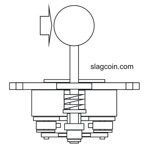
In this position, the joystick is in neutral. It is not in any one direction.

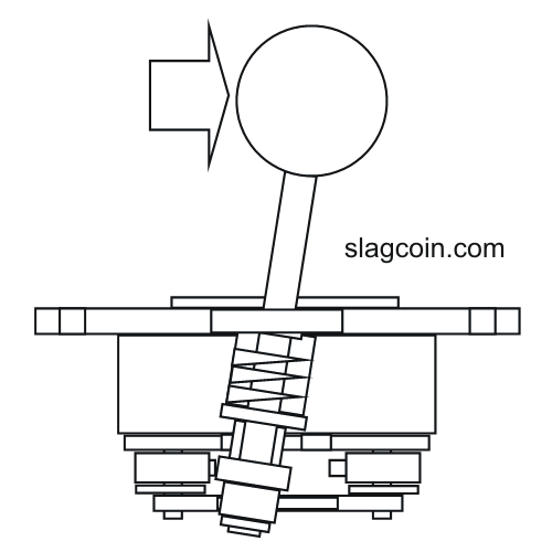
In this position, the actuator (at the bottom) is fully pressing a switch that looks much like this:

http://www.paradisearcadeshop.com/59-302-home/50-gram-micro.jpg

When the red plunger is pressed down, it connects two wires together, just like buttons, and then it is handled by the Integrated Circuit much like before.

There are also optical joysticks which use light to perform the same process of connecting two wires, but that is more than needed to be known. Analog joysticks are also beyond what is needed to know, as arcade joysticks use digital controls. Digital controls are the ones that we have just discussed, and that is that it is a “all or nothing” principle. You will be pressing a button or you won’t be. Simple as that.

Chapter 2: The golden rules

Now, we need to describe the difference between common ground and non-common ground. As we have just discussed, the buttons make contact between two wires. In a common ground controller, one side of every button will be a common ground wire. In a non common ground controller, buttons may connect to a specific voltage, but they do not all connect to the same ground wire. They may share a common line, or they may not. Here is an example of the wiring of a single button:

On the common ground side, there is a signal wire and a ground wire. This is important to remember. The signal wire will be at 5V in USB controllers (PS3/360). It is connected to the Integrated Circuit in some form, and when it is drops to 0V (Or ground), the IC then knows to send out the signal of the button being pressed. In common line PCBs, there might be a few wires at 4.73V, and a few that are not. When the chip reads the smaller drop in voltage, it knows that the button is pressed down. However, there might be another common line that is at 2.64V for a different set of buttons in the very same controller. Because of these differences, there really isn’t a “standard” that is as nice to work with as common ground of simply being either a high voltage or low voltage.

This picture will help show the differences in wiring of a full joystick:

In the common ground joystick, everything is touching a single ground wire, which makes it not only a bit nicer to work with, but also crucial in multi-PCB mods. Now, the non-common ground PCB in this picture shares a common line among the 4 directions, but only by the four directions. The buttons have different lines that they are connected to, which can make a mess of things even moreso than the common ground PCB.

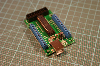
Most production joysticks have common ground PCBs. All Madcatz sticks have common ground PCBs, many newer Hori sticks (such as the VX/V3-SA/SE, or premium VLX are all good to go), the paewang, etc. use common ground PCBs. If your stick doesn’t use a common ground PCB, such as a Hori EX2, you can always gut PCBs from controllers or buy some of the custom PCBs made specifically for joysticks, more on those later.

The second golden rule is much easier to explain. By being powered, that means that both PCBs must be connected to the voltage or VCC (Common Collector Voltage) line, as well as each other’s ground wires, to ensure that power can go in, and also come out. The VCC line is always reachable from the +5v (red wire) of USB PCBs, but some of the other custom PCBs available have dedicated VCC lines. The two must be connected, as well as any of their ground wires. These are very prominent, but you can always search for the Ground (black) wire of a USB PCB. Custom PCBs also often have dedicated GNDs on their PCBs, and many production PCBs also have many points to connect ground to.

Sometimes, though, you may want to use a non-common ground PCB. A prime example is the PS3 SIXAXIS/DualShock3 controller PCBs. Neither of them are common ground, but they are the only PCBs you will be able to use if you desire a wireless PS3-compatible joystick.

Sony’s line of Dualshock controllers are notable for being non-common ground, but can be solderlessly hacked. More information on this process can be found here: Joystick Controller - PCB and Wiring

Also due to the fact that dualshock PCBs are not common ground, most people use the digital PS1 controllers, as they are common ground, and are all that we need for a PSX/PS2 PCB. PSX is also one of the favorite PCBs to use for converting to different systems.

Chapter 3: Double Duty

Now we move to connecting PCBs together via the signal wires that we just discussed. Recall that the signal wires are the wires that are set to be at a higher voltage, and when they touch a ground wire. Every button and d-pad direction on a common ground PCB will have one signal wire.

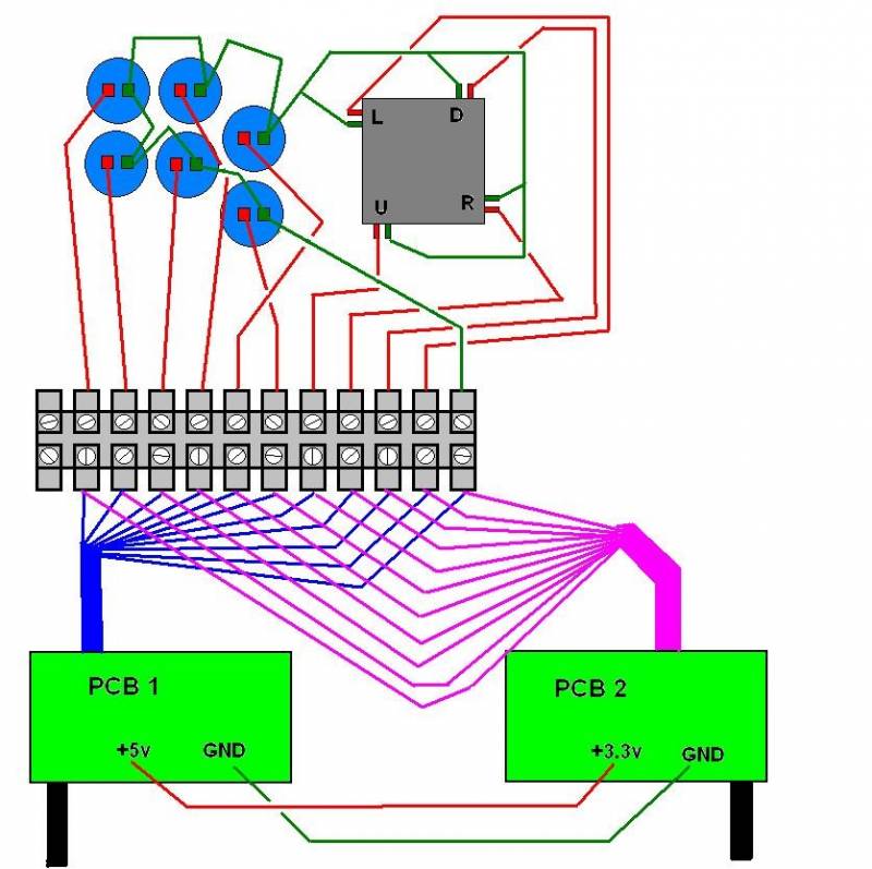
Now, if we combine both signal wires onto a single point, in the most brute of ways in this case, by connecting both signal wires to a single lug of the button, consider what would happen if we pushed that button. Both the X button of the PS3 PCB and the A button of the 360 PCB are now ground wires, and both PCBs read the buttons as being “pressed”. In this example, we haven’t yet discussed how to combine both USB wires into a single outgoing USB cord, so I have left both going out.*

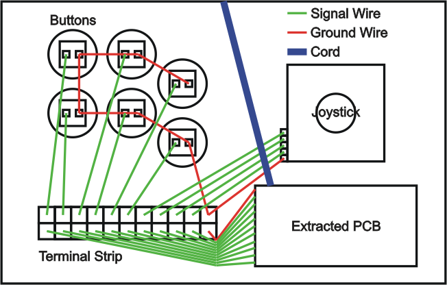
In this case, the signal wires are connected into a single wire connected to the lug. This is perfectly fine, and is electronically the same as the other picture. As long as both signal wires are touching the button they are to be connected to, as well as each other, then you will have “dual modded” the single button. Of course, the process needs to be repeated for all buttons and the joystick. For a way to combine the two wires into one, you could use a terminal stip like this:

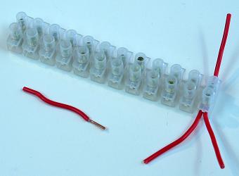
There are other options, such as butt connectors, stuffing both wires into a single quick disconnect, etc.

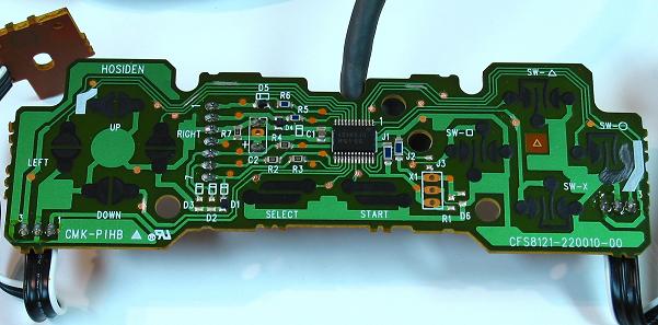
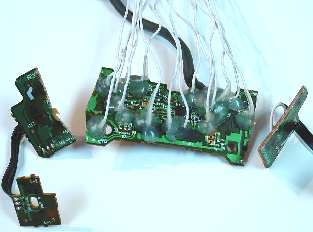
This is a third form of dual modding, where we assume a pre-wired stick. The Ground and signal wires are already connected, to the button, so we connect the new PCB directly to the existing PCB. For an example, this is one of the most common dual mods done-adding a ChImp PCB to the madcatz PCB included with SE and TE fightsticks:*

http://desmond.yfrog.com/Himg214/scaled.php?tn=0&server=214&filename=chimpmadcatz.png&xsize=640&ysize=640

Now, this picture clearly labels which points on the Madcatz PCB are the ground, signal, and USB wires (used later for combining both down a single USB cable). Since it is already wired to the stick, this method of soldering directly to the PCB is best because you will only add new wires to the stick, and not have to rewire the entire stick to accomodate the new PCB.

Once you perform this process of connecting signal wires after connecting VCC and ground wires, you will have finished a dual-PCB mod. However, you still haven’t connected the two USB cables together yet, and that will be the next chapter.

Chapter 4: Combining USB cables

Now, if you have an existing stick, you probably have one USB cable hanging out, and you don’t really want to have two hanging out. Not only does it look tacky, but accidently plugging both into a powered USB port would cause double the current to flow through the PCBs, potentially damaging your stick, PCBs, and your console or PC’s USB port. There are two options you have for this: a physical switch, or a PCB that supports console switching.*

There are many types of switches, but the one that we are interested in are DPDT, that is double pole, double throwing. Double pole means that two wires go in, and two wires come out. Double throwing specifically means that instead of being a simple “on-off” switch, much like pushbuttons, that the switch switches between two sets of wires.

This picture demonstrates a DPDT. When turned one way, the green wires become the center, outgoing wires. When turned the other way, the outgoing wires are the two wires that are red.

This is useful for our dual system mod, because USB uses two wires to send data to the console or PC it is connected to. The white wire is Data-, while the green is Data+. Because VCC and Ground are connected to obey the second golden rule, they are shared, and don’t need a switch. We can switch between the two system’s data wires like so:

The unsused console’s data wires are left unconnected and are not read by the system. The secondary PCB continues to send out data as if connected to a console, but the data doesn’t connect to the console at all, and is lost.

The next option is to use a PCB that supports USB console switching. One board that is dedicated to this function is the Imp PCB. It looks like this:

As opposed to needing to mod your case to fit and mount a switch, this small PCB can be connected in to switch the USB wires instead. The top four holes are to the outgoing USB wire, and this board must also be powered by connecting ground and VCC to the appropriate points. 1D+ and 1D- are your primary data wires, and will automatically be outgoing. 2D+ and 2D- are your secondary data wires, and will be outgoing if you ground the Guide point when you first plug the stick into the system. Normally, you would just wire your guide button to this point, and hold the button down if you wanted to play on your secondary system. However, in the case of madcatz TE fightsticks, you can solder a wire from the “RSTICK” point on the turbo panel PCB, as this grounds a signal wire in itself, just like a button. Since “RS” typically kills your stick’s movement, when you switch it to RS on startup and wired this way, it will switch the console over.

Just remember, the logic of the imp is the same as any other PCB reading for button inputs. If the Guide point is read as a low voltage, then it assumes the button is pressed. Else, it doesn’t assume the button is pressed and doesn’t switch the console.

There is also Master Strike, which can also switch USB, but it is recommended for advanced users only: Master Strike PCB : The Intelligent Control Center

Now, auto-detection is possible down USB, but that will be for next chapter.

1 Like

Chapter 5: Custom PCBs

Now, a lot of PCBs are made just for the dual mod in mind, and most custom PCBs are for 360 to PS3 dual mods, which makes the 360 dual mod the “easier” and preferred route of most modders. That is not to say that a PS3 to 360 dual mod isn’t possible, it is just the route that fewer people take. Note: it is totally possible that I may have missed a PCB. Please let me know if I need to update this list.

Custom PCBs are nice because they usually have very friendly points to solder to, or screw terminals to connect solderlessly, and are made with the modder in mind.

PCBs that do not auto-detect*
These will require one of the methods listed in the previous chapter to share a USB wire with another PCB.

PS360 By: Akihabarashop.jp (also available at focusattack.com/canadianjoysticks.com)

(Currently not in production, PS360+ to be soon)

The first custom PCB of its kind, and that is, the first to support xbox 360. It also supports PS3 on the same PCB,and uses screw terminals for a totally solderless dual mod on a single PCB. However, it does not support console auto-detection, and is best resevred for builds from scratch. It is slightly more expensive than other custom PCBs, but has the plus of having both consoles. It is overkill to use this PCB in an existing stick’s dual mod, because an existing stick will already have one of the consoles. It is fully common ground. PS360 Install Primer: http://www.beckfolio.com/download/PS360.pdf

Cthulhu/MC Cthulhu By: Toodles (Available from many retailers)

One of the favorites of the modding community, the Cthulhu PCB is a force to be reckoned with. The normal Cthulhu is a PS3 and PC PCB (As a Universal Human Interface Device, so it will work with all chipsets on any OS). However, a community favorite is the MC Cthuhlu for its ability to play all the favorite consoles of this generation (barring 360 and Wii titles that don’t support Gamecube controllers), the last, and many more. For a full list:http://forums.shoryuken.com/t/the-official-cthulhu-and-chimp-thread-try-our-new-dreamcast-flavor/45730 However, if you’re looking for a tutorial for the ultimate multi-console set-up, rtdzign has got you covered: http://forums.shoryuken.com/t/rj-45-mc-cthulhu-imp-xbox-360-dual-mod-tutorial-diagram/92427, or if you plan to mod an existing SE or TE fightstick: http://forums.shoryuken.com/t/installing-an-mc-cthulhu-and-imp-in-an-xbox-360-sf4-se-stick/61647. The Cthuhlu also has to option to be later upgraded to the MC version without the need to buy a new PCB, which is the one thing that makes it a viable option as a PCB without auto-detection.

Update: Imp V2 with Cthulhu or MC Cthulhu now auto-detects!

Project Leo/ Leo board By: gummowned (available at akihabarashop.jp)

http://akihabarashop.jp/images/LeoV2Fr.jpg

Leo board, version 2

This PCB in itself is not a controller PCB, but a very handy PCB for wireless dual mods. I mentioned earlier that the PS3 SIXAXIS is not common ground. Well, this board forces the PS3 SIXAXIS to be common ground via ribbon cable (plus some rare DualShock 3 PCBs, but SIXAXIS is generally more recommended, as it always has the ability to be used with a ribbon cable). I also mentioned that (late model) 360 official microsoft wireless controllers are common ground (except in the triggers). Now you can use both PCBs in conjunction for a wireless dual mod. It also has a huge battery slot (optional, as you can use the smaller PS3 SIXAXIS battery with no problems to power the whole thing) for extended wireless use in a dual mod. More info can be attained from its thread: http://forums.shoryuken.com/t/project-leo-sixaxis-wireless-360-dual-mod/68438

Paewang Revolution PCB By: Paewang (available at etokki.com)

Not exactly a “custom” PCB, but this is a pre-dual modded PCB used by a lot of custom builders for being so small, easy to use, and already dual modded. Its functionality is almost the same as the PS360, but this does require soldering. It was originally intended for the Paewang Revolution joystick, but most people don’t like the quality of the stick at all. In fact, the primary seller offers you the option to buy just the PCB without the shell at the same price to save on shipping.

PCBs with auto-detection
These PCBs feature spots for the xbox data wires to be soldered to, and will hand off the data wires to the appropriate system automatically.

ChImp/ChImp SMD By: Toodles (Avilable at lizardlick.com)

SMD version

ChImp kit (No longer in production)

The Cthuhlu counterpart that is not only a PS3 controller, but also can detect when it is connected to a 360, and switch its outgoing USB wires with the 360 wires automatically. This is usually the preferred PCB for 360 to PS3 dual mods. The SMD version is your best bet if you want it pre-assmebled, while the kit is slightly cheaper. The SMD version also features console status LEDs, as well as much better trigger inversion, should you require your triggers to be inverted (more on that later, for most existing sticks, though, this is not an issue). The SMD version also comes with screw rerminals, and requires no soldering (However, connecting this to a 360 PCB may require soldering, depending how you mod it). The only disadvantage it has against the Cthulhu is the lack of MC support, as it will always be a PS3 controller, and the auto detection costs the PCB the possibility of multi console support.

DualStrike/DualStrike SMD By: benaco74 and gummowned (SMD version) SMD version is available from gummowned direct, while the original is avilable from Dual Strike - ArcadeForge

A handful (20) of DualStrike SMDs (Currently not in production)

Original DualStrike

A solderless alternative to the ChImp is the DualStrike board. With its latest firmware update, it can now also auto-detect consoles, and also has the ability to play Xbox (original) on the same PCB, and can connect to a ribbon cable in conjunction with TEasy (linked in introduction) to make for a fully solderless dual mod.*

DualStrike SMD is a bit of a different beast, and while it runs on the same firmware, it is much smaller, and much more suitable for dual mods of a pad, or smaller cases. It is a nice alternative to the ChImp PCB, but definitely requires soldering. It also runs Xbox 1, and both versions are also Universal HIDs like ChImp and Cthuhlu PCBs. Aditionally, it also can output dedicated analog controls much like the Madcatz PCBs.

TEasy Strike By: Phreakazoid 187 (available at phreakmods.com)

This is DualStrike and TEasy on a single board. Fully solderless, and screws right on. Uses Dualstrike as a main controller, and Phreazoid’s own TEasy to screw in for a fully solderless mod.

Kitty boards By: Toodles

TE Edition Kitty

Toodles’ own solderless PCB for the TE and VLX 360 model joysticks. This is a bit more difficult to install than the TEasy Strike, but it is much easier than most boards to use. It also includes (optional) Multi-console Cthulhu support with button remapping and auto-detection. The VLX version also doesn’t void your warranty by installing it! If you’re considering using this or the TEasy strike to Dual mod your stick, this thread is not for you.

Chapter 6: Padhacks (See also: http://forums.shoryuken.com/t/the-padhacking-thread/16708)

Padhacks are an alternative way to gain PCBs, and by learning the process, you will always be able to gain the PCB for the system you need to add in. Remember, the golden rules say nothing about your PCBs having to be PS3 and 360, or that you have to limit yourself to two! As long as you have space, you can add additional common ground PCBs to add in many more systems (USB permitting, as enough PCBs will cause the whole stick to drain more than 500mA of current, the max amount of current any USB device may draw before the device will be disconnected automatically). However, for super-multiconsole goodness, you should also check out: http://forums.shoryuken.com/t/rj-45-mc-cthulhu-imp-xbox-360-dual-mod-tutorial-diagram/92427

Remember back in chapter 1 about the button’s way of working on a pad?*In the case of common ground PCBs, it is simply done by grounding a signal wire. This picture is an example of a close look at a single contact in a pad:

Normally, the two split halves are contacted by the rubber contact suspended above it. However, if we were to solder a wire to the side that was the signal side with the high voltage, and connect the other side to ground, we’ve discussed how the microswitch does the same exact job as the rubber contact. When the button is pressed, it will be exactly the same as if the rubber contact had connected the two ends.

This is useful to us, because it allows us to harvest PCBs that are not made custom, most notably, xbox 360 controllers. It is also important that these PCBs are common ground. The madcatz fightpad is likely the favorite to padhack purely for its ease of use, and that is it cheap (Easily $20 from buy.com or amazon).

The madcatz model 4716 (madcatz gamepad) is also common ground, but it has the tricky part of its triggers in later models, which have their signal set to low by default, as opposed to high. To invert them is no easy process, and is detailed much better here: http://forums.shoryuken.com/t/how-to-padhack-an-08-09-madcatz-4716-common-ground-xbox-360-pad/70617 The process itself, though, is much harder than if you had simply bought a fightpad. ChImp SMD can do the inversion for you flawlessly, and this would be the best option if forced to use a 4716 over fightpad.

Microsoft official controllers should be avoided, as they are not common ground, except in the triggers. The only exception is if you plan on using it wirelessly, which is common ground, except in the triggers.

The process of a padhack is very simple. Solder wires to every signal contact, and one to ground. Then connect a signal wire to the appropriate button or joystick direction, or connect it to your other PCB which is already wired to the stick properly. If using in a dual-PCB setup, you must connect the VCC line, as well.

However, finding which side is signal, which side is ground, and if the controller is even common ground is difficult without looking at the PCB. To help, diagrams are available in the padhacking thread linked above, as well as on slagcoin, Joystick Controller - PCB and Wiring

These resources already tell you exactly where to solder, however, there are other ways to tell, if you were ever faced with the case of finding a $2 controller at a pawn shop, and seeing a golden opportunity for a cheap PCB.

The first, more difficult option, but requires no special tools is to follow the trace of the PCB.

On most PCBs, there are two tones of green. The dark green is not connected, while the light green is. The darker green will usually be used as insulation to separate the light green traces.

By following the light green trace, you can see which end is connected to the main IC, and the other end may not have a trace going out at all (Because it is connected to the common ground, like everything else). However, the other end may connect itself to other contacts. This is a tell-tale sign that it is a common ground.

Here is an example of a digital PSX PCB:

Now, to add illustrations to following traces:

As far as the triggers are concerned, they are the two rows of three points at the bottom left and bottom right. One is Ground, and the other two are signals for each.

The PCB has been scraped along its traces because the contacts are carbon, and are not friendly for soldering. Scraping it with a knife, rotary tool, or otherwise, exposes the copper of the traces, which is much more solder-friendly. It also allows the PCB to be cut, like so:

However, following the trace is handy because if a contact ever breaks off, you can follow the trace, and solder to any point farther down the trace. This happened to me when I was doing a PS3>360 dual mod, and even with stable soldering with flux and hot glue, the Guide contact of the madcatz fightpad just flew right off. Following the trace back up allowed me to solder to an alternative point, and quickly fix the problem.

Now, the second, and easier way is to use a multimeter to test for continuity. It is much easier, because you can always check PCBs for their commons using this. You can get away with a cheap, analog one that has a needle, but a digital one with a beeping continuity tester is a much nicer asset.

To test for continuity, turn your multimeter to resistance (or beeping continuity, if yours has that function), any threshold works. When you touch both probes to something that is electrically connected, resistance will drop to 0 (or your beeping continuity tester will begin to beep).

The way that we can use this is that every ground side of the PCB will have continuity, because the ground is always connected to itself throughout the whole PCB. There are four ways to test two separate contacts (color doesn’t matter when testing resistance or continuity, it simply will tell you if the two probes are touching two points which are electrically connected):

When the continuity tester either beeps, or the resistance drops to zero, then those are both ground contacts, and the other two are signal contacts. From now on, you can test the rest by keeping one of the probes on that ground wire, and test both sides of every other contact to find which is ground. Using a marker to put a dot on the side that is ground is handy to remember which side is ground, and the other side will be signal. You can always use any amount of the grounds to connect to buttons, joystick, other PCB, etc.

Once you have soldered wires to all of the signals that you intend to use, this picture is how you would wire it in your stick (the terminal strip is optional):

Of course, you may connect it to another PCB if you’re working a dual mod, something like so:

Terminal strips again, optional.

1 Like

Chapter 7: Soldering

Now we come to one of the big points that I feel scares a lot of people from modding?The soldering. It’s heat and electronics and it seems like a whole mess of bad can await you. But, with a bit of practice, you too, will be able to solder.

There are a lot of “solderless” hacks and work arounds, and while they certainly work, I don’t think they’re quite as stable. Would you rather the buttons that you’re relying on in a tourney to be held together by some tape, or hard metal soldered onto metal? That’s why I recommend TEasy if you really want a solderless dual mod, because Phreakazoid187 put some serious effort into it to make sure that board was stable and effective.

First off, we need some tools?

Soldering iron and solder, for obvious reasons. Don’t get the lead-free stuff, unless if you’re super paranoid about heavy metal poisoning. It’s way more expensive, and I usually have much better solder joints with leaded solders. As far as specifics, you can get an iron in the 10?20W or so range to get most jobs done starting out. Higher heats allow you to work faster, but the pace for these irons is probably not the ideal pace for a beginner. Don’t expect to pay more than $10 for a decent iron. Get the thinnest gauge solder (Usually classified as “light duty” by radioshack), that’s as thick as we’re going to need for working on the PCBs of arcade sticks.

Desoldering instrument. I have a desoldering pump pictures, but I really like braided copper more. Anything you may accidentally solder together can be desoldered, and that’s why having the ability to remove any mistakes is crucial, especially if you’re a beginner.

Pliers, Diagonal and needle nose. Needle nose are good for getting a tight grip on small components, or holding anything that may get hot while soldering, especially braided copper, which gets very hot when using. Diagonal nose pliers (AKA wire cutters) are good for trimming off the excess leads of components when assembling PCBs, and can be used in a pinch to cut (and possibly strip) wires.

Wire. For making connections. Stranded is your best best for ease to work with. Solid core works just as well, but it can break off easier, is a lot more firm, and is just a hassle. Generally, 22 gauge AWG wire and higher is the preferred gauge among modders.

Wire strippers. The cheap ones at radio shack (RadioShack? 8.5" 4-Way Crimping Tool - RadioShack.com) are all you really need, and pretty much everybody has a pair of them. They come with crimpers, which are nice for crimping quick disconnects, should you ever wire up a stick from scratch. I like more expensive ones, like the pair pictured, because they strip wires with ease, little effort, and are more ergonomic, but they don’t crimp.

Wet sponge. Good for cleaning your soldering iron tip. You can get by fine without it, but it’s good to clean your tip off of excess solder to help increase precision and reduce mistakes.

Screwdrivers/Allen keys. For opening and closing your arcade stick. Small flatheads are a good call, they make removing snap-in buttons a breeze, if you’re ever so inclined to swap them. Also useful if you’re working with screw terminals or barrier strips. A small flathead screwdriver is also nice to have so that you can use it to remove button caps from buttons, use it to pry off E-clips from joysticks, and what have you.

Hot glue gun (optional, but recommended). Secures wires to circuit boards, making it harder for them to break off, and add additional adhesion. At only a few bucks, and the likeliness of your household having one, you might as well keep it on hand to work with.

Flux(optional). Makes soldering a breeze by making solder flow easier, and in turn, stick better. It is optional because most solders are rosin-core solders, and they have flux in them. But additional flux is a huge help, especially when moving down into tinier sizes. It comes in liquid and paste forms.

Helping hands (optional). Just when you needed a third hand, helping hands will hold things in place! Include two alligator-clip “hands” and a magnifying glass to hold More expensive models (And I mean like $4 or $5 more than this one I got for maybe $3) feature solder ing iron stands/sponge holders.

Multimeter (strongly recommended). Most of the usages listed in the previous chapter, especially that nice continuity tester than can help you detect a short circuit to fix problems easier than before. Use that continuity test from last chapter! You will be able to diagnose connections easier, and it is very helpful in identifying many problems. A must for modders, but definitely an expensive too (for a good one). You can try to skip this one, but you will find it hugely to your benefit after you’ve had some experience.

There’s probably plenty of other combinations possible, but this is what I like to use. You may be able to get by with less, but, again, tools do cost money, and you need proper tools to do the proper job. The costs can really stack up, and you may skimp, but then realize you actually needed something. And some things may seem pointless, such as helping hands, until you actually get to a point where having an extra set of hands would be a huge asset. Again, you may want to add up material costs and weigh it against simply hiring a modder instead, especially if you only plan to mod one stick. These guys have experience, and any mistakes they make will definitely be fixed before they return it to you.

Now, at this point, it’s going to get a bit heavy on the pictures and diagrams to try to explain this as best as possible. In reality, though, nothing beats out experience, so you’re going to have to try things and see what you like best in order to work more efficiently.

Now, mostly, I am going to simply focus on soldering wires to PCBs, because this is generally about the soldering you need for most mods.

Because practice is important, I’d look at picking up a radioshack prototyping PCB. I had a full one, but I only had two small pieces left to practice with, so I’ll be using those in the future.

On one side, it is gridded for reference, but the other side has the copper holes to be soldered to. It is important to remember that solder sticks to metal, and is essentially “electronic glue” between metals. When heated, solder melts down to a liquid form, and will stick to any hot metals, namely, the tip of your soldering iron.

It is normal to smoke when heated. It is the rosin core burning off. It is what allows the solder to flow and stick, and if you use additional liquid or paste flux, it will similarly cause existing solder to flow more and stick more. But, the solder will often times stick to your tip, which is what the wet sponge is for, cleaning and removing the excess.

Now, I will say, this PCB is really small for beginners, and one set I really like is the elenco Learn to Solder kit. Amazon.com: Elenco AmeriKit Learn to Solder Kit: Toys & Games It includes a basic PCB with practice zone, soldering iron, all components (except a 9V battery), a handy guide, and enough materials (Solder, desoldering braid, and diagonal nose pliers) to put it all together. If you can do the work I describe on the Radio Shack PCBs just fine, then don’t sweat getting this, but if you want some really good practice, it’s a worthwhile kit to get started with.

To begin, we will start with your basic through-hole soldering. It is done by threading the component you are trying to solder through a hole (hence, through-hole), and then melting solder over the top of it to “glue” it into place, as well as electrically connecting it. This diagram will help.

Now, in reality, you want to strip a few millimeters of wire to make sure it goes entirely through the PCB. This is a bit more than you want for most projects, but this is practice, so it’s okay.

Then, thread it through for soldering.

Now, when it comes to soldering, there are a few different ways to do this, but I’ll try to demonstrate a few. You’ll have to eventually find what suits you best, but these are the ones I like to use.

First off, we will start basically. Recall that solder likes to stick to hot things. So, we need to apply heat to where the solder is going to stick to. So, begin by heating up the contact that you’re going to be soldering to.

Don’t heat the wire, because there is more surface area on the PCB’s contact than the wire. Once you’re properly heating it, time to apply solder.

The solder will melt and spread across, but try not to use too much. It takes practice to know how much to use.

With actual pictures:

Now, at this point, you could have made a mistake if you use too much solder, one of the most common results being a solder bridge. This is when solder leaks over from one terminal to one it’s not supposed to, creating a short circuit. It is very commonly caused by using too much solder. It would look something like this:

To remove, this is what a desoldering device is handy for. Use it to remove excess. With a pump, you will heat up the joint, and then push down the button on the back to have it readied, then push the button on the side to suck up the hot solder (Which remember, is like a liquid, so the pump will suck it right up). If using braided copper, hold it with pliers (It gets very hot), and apply heat to the solder. Because it is hot metal, the solder begins to go up the braided copper and off of the PCB. I am just using a pump to suck away the excess.

Fixed.

Another common problem is a cold joint, and this usually occurs by not heating up the contact enough. The joint will look dull, instead of metallic and shiny. Generally, these are very weak, and break easily, and also don’t make a solid connection. You should remove the offending solder and try again.

This is a cold joint.

Now, there are a few other ways to apply solder to this bad boy. This next way is helpful if you don’t have your other hand available (Because it may be holding something).

First, melt solder over your tip (Because it will stick to the tip), and then put the solder down so you can use your off hand for whatever.

Then, drip it over the joint to be soldered.

Now, my personal favorite is more of a combination of the two before that. I bring the solder and tip together over the contact to heat it, melt solder, and pull them apart for a clean joint quickly. This certainly takes practice to learn, and a hot iron to do it well. However, it will cut down the time you spend soldering quite a bit, and as I said, it is my personal favorite.

With a bit of practice, and able to cleanly do many Through Hole joints, it’s time for the real test, and what soldering on most controller PCBs is about, the surface mount soldering. This is where you solder a wire directly to the surface, because a lack of convenient hole (As most manufactures aren’t designing their PCBs for easy wire access).

To do so, we must introduce a new concept: tinning. Now, I didn’t do this with the through hole stuff, mostly because it made my wire too fat to go through the holes. Tinning is coating a wire in solder in order for it to be easier to work with while soldering, especially on the surface. To do, simply melt a bit of solder over the wire.

In reality, done neatly, it’ll look like this:

Usually this causes the insulation of the wire to shrink back due to the heat, so you may need to clip off some excess wire. You really only need about a millimeter of wire exposed. The rest should be covered by insulation. This is to prevent over exposing the wire, which could cause a short circuit if it moves too much in any direction, by touching something nearby that it was not intended to touch.

This is about how much I go for:

Now, I figure you’re familiar with these diagrams and soldering a bit if you’ve managed to stick with me this far, so here’s what it would look like on a diagram level:

(Assuming the wire is tinned, it would work nicely. Now, you don’t have to put solder over the contact. But it helps. There’s no “set” rule of how to do it. You just need to figure out what works best for you)

Now, with actual pictures.

However, sometimes, this is very hard, and it’s a good time to bust out the flux. Just apply a little over the area you wish to solder to.

A bit more solder than I would have liked, but I’m okay with it.

This is ideally how skilled you want to be able to be, if you can solder several wires next to each other this closely without any bridges or mistakes, then there’s probably very little in the world of joysticks you can’t solder.

Also, a note about hot glue. In this picture, the one on top has hot glue directly on the joint, which is not good. Hot glue should be slightly away from the joint so that it holds the wire down in place, like the on on the bottom. It also helps take tension off of the joint to ensure that it won’t break off.

That’s about all I could think of. If you have any questions, additional input, or what have you, got ahead and leave a reply. And thanks for sticking through that whole guide. I’d love to hear any feedback from any and all community members.

Reserving this space for later use, if necessary.

Very nice, a lot better than repeating yourself 50 times anyway :smiley:

The diagrams are making a lot of things clearer, but I just started reading. Thanks for writing this!

Great write-up for the average user. Thanks. Nominated.

Great job Nerrage! :tup:

So could you explain to me how to dual mod??

j/k

Good shit Nerrage, this will help a ton of people out!

Nominated for sure

Thank you Nerrage for putting up the soldering tutorial!

Step 1: Do your research
Step 2: Shop for parts
Step 3: Realize how much you’re spending, chicken out and then have someone do it for you.

There is no shame in this…

Good read Nerrage!

It’s all about supporting the community and making sure that those who do this kind of thing can get a bit of compensation.

Great guide! I’m sure a lot of people learning to mod will find this very useful. :cybot:

Wow nice write up dude! You should add this as well.
http://shoryuken.com/f177/project-leo-sixaxis-wireless-360-dual-mod-194525/
Gummowned likes to break the golden rules. :wink:

0_0. Whoa, thank you!

Pretty much. I tried to make a point in the intro that hiring someone > DIY, unless if you really want to, and/or enjoy this sort of thing.

I’ll add that up in the custom PCBs section. Thanks.

And to everyone else, you’re welcome! It’s my pleasure.

Great work up Nerrage.

Good shit dude BUT, MC Cthulhu does autodetect which console is on, you might want to write that for the people that do not like newfaggotry consoles :slight_smile:

The basis is on sharing a USB, and it’s just easier to have them both listed under one, because they are similar.