Introduction
This guide is aimed to give newbies a full understanding of the workings of PCBs in controllers and arcade joysticks, the process of the dual mod, and shouldn’t be considered a simple “Step 1, do X, step 2, do Y.” I highly recommend you grasp an understanding beyond “Connect this to that, etc.” If you are willing to take the time to read and understand farther beyond a step-by-step process, not only will you find the process easier, but you will also be able to troubleshoot more effectively, and in turn, be a much better modder than someone who only understands it as a process. This also doesn’t intend to be a simple guide for dual modding X model stick from Y system to work now on Y and Z system, which certainly stretches the length out as well.
While most of this information is already out there, I aimed to make this a more “complete” guide, which will not only work for one case of a dual mod, but will work for many more cases, and will be in simpler, more explained terms than many other guides out there.
I haven’t found a guide quite as complete as I’ve attempted to make this one, and I’ve tried to make it a comprehensive source to answer most questions about the full process of dual modding a joystick.
If this guide is too lengthy for you, then I recommend looking into hiring a modder or skilled technician as opposed to doing it yourself. You can check http://shoryuken.com/forum/index.php?forums/trading-outlet.341/ and Need a Modder/Builder in Your Area? Check This Post for modders. Another option for owners of Tournament Edition Madcatz fightsticks is http://forums.shoryuken.com/t/official-teasy-thread-teasy-strike-is-here/99430 and Official ‘Kitty’ class boards thread These are the only stable solderless options I would recommend. Just remember, it may seem more “expensive” to hire someone, but when you DIY, you have a lot of equipment to buy, and then you may realize “I need a desoldering braid, and then I ran out of wire, and these strippers don’t crimp, etc.” and end up spending more for equipment you may never use again. This is especially in the case of planning to dual mod only one stick. Certainly, there is a sense of pride in doing the mod yourself, but the cost of tools can be quite hefty for being used only once. Regardless, this guide aims to be a helpful reference to first timers.*
Also, moreover as a note, I named this “dual modding 101,” because that was what I intended, but when I continued to realize the greater amount of material needed to cover everything in a general direction, it continued to branch out into more and more of a guide than before. Any additional input is welcome, and my illustrations may leave some room from improvement. Heh. A lot of imagery is borrowed from slagcoin.com, and is also an excellent read for anyone wanting to get deaper into custom joystick making.
Chapter 1: The nature of a single button
While this may not make sense to be starting off with, it is crucial that you understand how a single button works before we can move any further. Buttons work the same on both arcade sticks and controllers, and that is by acting as a simple switch. The main difference between buttons of an arcade controller and that of a pad controller is the method of how they act as a switch.

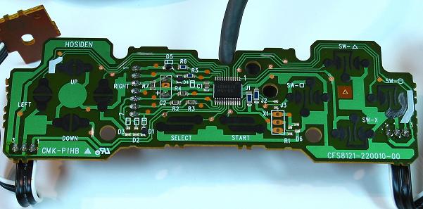
Now, on the left, the controller’s buttons work by being suspended over the PCB, that is, Printed Circuit Board, the board that holds all of the electrical components and connects them together on a single board. It is suspended by a rubber contact, which has a small piece of metal at the top. Normally, these do not touch, but when the pressure of your thumb pushes the button, it makes this tiny piece of metal touch two parts of a PCB together.*
Arcade joysticks use microswitches as opposed to rubber contacts. However, they work nearly identically. When pushed, the microswitches connect the two wires connected to the button, much like how rubber contacts connect two points of the PCB. These wires are typically connected to a PCB.
In either case, when the main Integrated Circuit, IC, or sometimes called “microchip” senses that the two wires or points on the PCB are connected, it sends a signal to the system that the button is pressed, which is handled by the game, etc.
At the same merit, D-pads and joysticks work exactly the same as single buttons, but they are simply shaped differently. The D-pad works exactly the same as buttons, that is, rubber contacts suspended over PCBs. Joysticks differ slightly from buttons, though. They still use microswitches, but they are shaped quite differently, because joysticks hit microswitches sideways, while buttons hit them from above. These pictures demonstrate a joystick in its neutral position moving to press the microswitch down all the way (or what is called the throw)
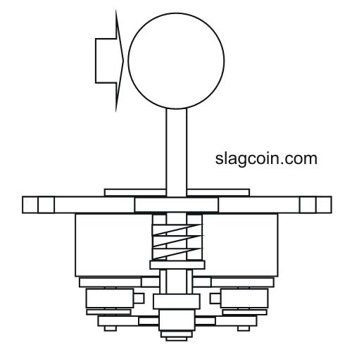
In this position, the joystick is in neutral. It is not in any one direction.
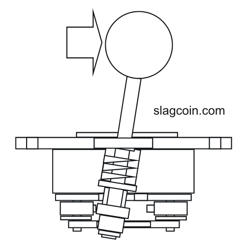
In this position, the actuator (at the bottom) is fully pressing a switch that looks much like this:
http://www.paradisearcadeshop.com/59-302-home/50-gram-micro.jpg
When the red plunger is pressed down, it connects two wires together, just like buttons, and then it is handled by the Integrated Circuit much like before.
There are also optical joysticks which use light to perform the same process of connecting two wires, but that is more than needed to be known. Analog joysticks are also beyond what is needed to know, as arcade joysticks use digital controls. Digital controls are the ones that we have just discussed, and that is that it is a “all or nothing” principle. You will be pressing a button or you won’t be. Simple as that.
Chapter 2: The golden rules
Now, we need to describe the difference between common ground and non-common ground. As we have just discussed, the buttons make contact between two wires. In a common ground controller, one side of every button will be a common ground wire. In a non common ground controller, buttons may connect to a specific voltage, but they do not all connect to the same ground wire. They may share a common line, or they may not. Here is an example of the wiring of a single button:

On the common ground side, there is a signal wire and a ground wire. This is important to remember. The signal wire will be at 5V in USB controllers (PS3/360). It is connected to the Integrated Circuit in some form, and when it is drops to 0V (Or ground), the IC then knows to send out the signal of the button being pressed. In common line PCBs, there might be a few wires at 4.73V, and a few that are not. When the chip reads the smaller drop in voltage, it knows that the button is pressed down. However, there might be another common line that is at 2.64V for a different set of buttons in the very same controller. Because of these differences, there really isn’t a “standard” that is as nice to work with as common ground of simply being either a high voltage or low voltage.
This picture will help show the differences in wiring of a full joystick:

In the common ground joystick, everything is touching a single ground wire, which makes it not only a bit nicer to work with, but also crucial in multi-PCB mods. Now, the non-common ground PCB in this picture shares a common line among the 4 directions, but only by the four directions. The buttons have different lines that they are connected to, which can make a mess of things even moreso than the common ground PCB.
Most production joysticks have common ground PCBs. All Madcatz sticks have common ground PCBs, many newer Hori sticks (such as the VX/V3-SA/SE, or premium VLX are all good to go), the paewang, etc. use common ground PCBs. If your stick doesn’t use a common ground PCB, such as a Hori EX2, you can always gut PCBs from controllers or buy some of the custom PCBs made specifically for joysticks, more on those later.
The second golden rule is much easier to explain. By being powered, that means that both PCBs must be connected to the voltage or VCC (Common Collector Voltage) line, as well as each other’s ground wires, to ensure that power can go in, and also come out. The VCC line is always reachable from the +5v (red wire) of USB PCBs, but some of the other custom PCBs available have dedicated VCC lines. The two must be connected, as well as any of their ground wires. These are very prominent, but you can always search for the Ground (black) wire of a USB PCB. Custom PCBs also often have dedicated GNDs on their PCBs, and many production PCBs also have many points to connect ground to.
Sometimes, though, you may want to use a non-common ground PCB. A prime example is the PS3 SIXAXIS/DualShock3 controller PCBs. Neither of them are common ground, but they are the only PCBs you will be able to use if you desire a wireless PS3-compatible joystick.
Sony’s line of Dualshock controllers are notable for being non-common ground, but can be solderlessly hacked. More information on this process can be found here: Joystick Controller - PCB and Wiring
Also due to the fact that dualshock PCBs are not common ground, most people use the digital PS1 controllers, as they are common ground, and are all that we need for a PSX/PS2 PCB. PSX is also one of the favorite PCBs to use for converting to different systems.
Chapter 3: Double Duty
Now we move to connecting PCBs together via the signal wires that we just discussed. Recall that the signal wires are the wires that are set to be at a higher voltage, and when they touch a ground wire. Every button and d-pad direction on a common ground PCB will have one signal wire.

Now, if we combine both signal wires onto a single point, in the most brute of ways in this case, by connecting both signal wires to a single lug of the button, consider what would happen if we pushed that button. Both the X button of the PS3 PCB and the A button of the 360 PCB are now ground wires, and both PCBs read the buttons as being “pressed”. In this example, we haven’t yet discussed how to combine both USB wires into a single outgoing USB cord, so I have left both going out.*

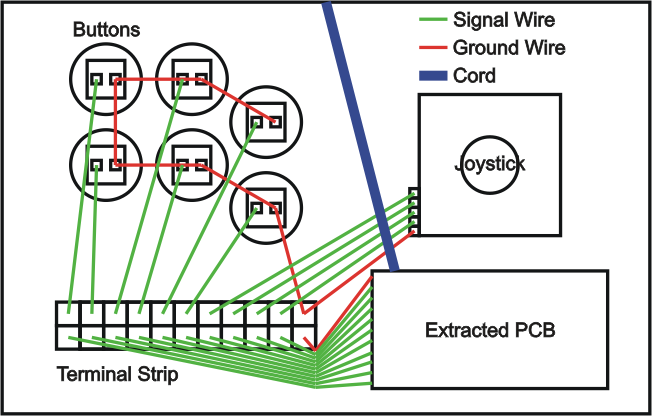
In this case, the signal wires are connected into a single wire connected to the lug. This is perfectly fine, and is electronically the same as the other picture. As long as both signal wires are touching the button they are to be connected to, as well as each other, then you will have “dual modded” the single button. Of course, the process needs to be repeated for all buttons and the joystick. For a way to combine the two wires into one, you could use a terminal stip like this:
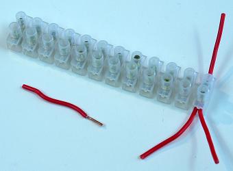
There are other options, such as butt connectors, stuffing both wires into a single quick disconnect, etc.

This is a third form of dual modding, where we assume a pre-wired stick. The Ground and signal wires are already connected, to the button, so we connect the new PCB directly to the existing PCB. For an example, this is one of the most common dual mods done-adding a ChImp PCB to the madcatz PCB included with SE and TE fightsticks:*
Now, this picture clearly labels which points on the Madcatz PCB are the ground, signal, and USB wires (used later for combining both down a single USB cable). Since it is already wired to the stick, this method of soldering directly to the PCB is best because you will only add new wires to the stick, and not have to rewire the entire stick to accomodate the new PCB.
Once you perform this process of connecting signal wires after connecting VCC and ground wires, you will have finished a dual-PCB mod. However, you still haven’t connected the two USB cables together yet, and that will be the next chapter.
Chapter 4: Combining USB cables
Now, if you have an existing stick, you probably have one USB cable hanging out, and you don’t really want to have two hanging out. Not only does it look tacky, but accidently plugging both into a powered USB port would cause double the current to flow through the PCBs, potentially damaging your stick, PCBs, and your console or PC’s USB port. There are two options you have for this: a physical switch, or a PCB that supports console switching.*
There are many types of switches, but the one that we are interested in are DPDT, that is double pole, double throwing. Double pole means that two wires go in, and two wires come out. Double throwing specifically means that instead of being a simple “on-off” switch, much like pushbuttons, that the switch switches between two sets of wires.

This picture demonstrates a DPDT. When turned one way, the green wires become the center, outgoing wires. When turned the other way, the outgoing wires are the two wires that are red.
This is useful for our dual system mod, because USB uses two wires to send data to the console or PC it is connected to. The white wire is Data-, while the green is Data+. Because VCC and Ground are connected to obey the second golden rule, they are shared, and don’t need a switch. We can switch between the two system’s data wires like so:

The unsused console’s data wires are left unconnected and are not read by the system. The secondary PCB continues to send out data as if connected to a console, but the data doesn’t connect to the console at all, and is lost.
The next option is to use a PCB that supports USB console switching. One board that is dedicated to this function is the Imp PCB. It looks like this:

As opposed to needing to mod your case to fit and mount a switch, this small PCB can be connected in to switch the USB wires instead. The top four holes are to the outgoing USB wire, and this board must also be powered by connecting ground and VCC to the appropriate points. 1D+ and 1D- are your primary data wires, and will automatically be outgoing. 2D+ and 2D- are your secondary data wires, and will be outgoing if you ground the Guide point when you first plug the stick into the system. Normally, you would just wire your guide button to this point, and hold the button down if you wanted to play on your secondary system. However, in the case of madcatz TE fightsticks, you can solder a wire from the “RSTICK” point on the turbo panel PCB, as this grounds a signal wire in itself, just like a button. Since “RS” typically kills your stick’s movement, when you switch it to RS on startup and wired this way, it will switch the console over.
Just remember, the logic of the imp is the same as any other PCB reading for button inputs. If the Guide point is read as a low voltage, then it assumes the button is pressed. Else, it doesn’t assume the button is pressed and doesn’t switch the console.
There is also Master Strike, which can also switch USB, but it is recommended for advanced users only: Master Strike PCB : The Intelligent Control Center
Now, auto-detection is possible down USB, but that will be for next chapter.


