Couple of questions about arcade cabinets

I can’t really recommend any of these items from first hand experience but they are a good general indication of what you need. I went with amazon listings because most people have prime these days. In the past I could send you to radio shack with a part number but those days are long gone.

Solder Pump
https://www.amazon.com/WEmake-WM-SP4-Solder-Sucker-desoldering/dp/B0002KRAAG

Or grab a 3 pack for a buck more!
https://www.amazon.com/Teenitor-Solder-Sucker-Desoldering-Removal/dp/B0739LXQ6N

Even better, Solder Pump with Solder Braid
https://www.amazon.com/AUSTOR-Desoldering-Sucker-Pieces-Solder/dp/B07CB9V427

This one’s slightly cheaper with less stuff but still has good reviews
https://www.amazon.com/dp/B0777LMVTT

You could spend more on electronic pumps, solder extraction stations, etc but you really don’t need much to get started. Monitor pcbs are large analog designs with large components and lots of room to work. None of that pesky surface mount stuff that you need the binocular scope to work on.

As for discharging the monitor, there is lots of info on google about how to do this safely and on the cheap. I am fortunate enough to have an 80KV high voltage probe with built in discharge in the toolbox. Trust me, you don’t need this tool unless you do this sort of thing frequently.

The tube is what stores the charge not the HV pcb. You will see videos out there about connecting a screwdriver to the monitor frame with a wire or alligator clip and then inserting the screwdriver under the anode cap (suction cup looking thing) on the monitor to discharge the tube. This works. Best suggestion here is the one hand on the screwdriver handle and the other behind your back rule. Never form a complete path for electricity between one hand and the other.

Long day here but you get the idea. Read up and be safe. When was the last time you heard of anyone killed by playing with a TV and it not falling on them?
1 Like

Thanks for all of that info.

After talking with a couple people, both of which said that I need a cap kit and probably a reflow, and possibly a new flyback, I think I’m going to take it to someone who is not too far from me. That Buffet guy is an hour away and he said I could bring the tube too and he could check out everything.

I just think with my minimal knowledge of this all, and if I really want to get it up and running in as good condition as I can, that having him do this instead would probably be better.

Okay I have a couple more questions now. I have my pi2jamma and it was pretty incredible how plug and play it was. But now I have to wire up buttons 4 5 and 6 for both player 1 and 2.

Player 1 and Player 2 buttons 4 and 5 are on pin 25 and 26, top and bottom, on the pi2jamma.

And that is where my questions come into play…

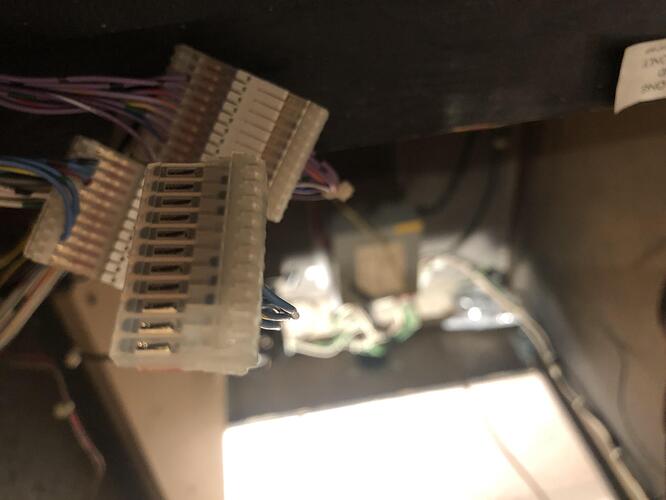
  1. Ideally I would like to create another “kick harness” that I can plug into my control panel. However, I am not sure what the name the connector is that connects to the control panel. Here is a pic of exactly what I am talking about, and I’m wondering what it is called so I can get another one.

  1. I need to add more wires to the JAMMA harness. I am not sure how to do this and am wondering exactly how it is done. Are there some kind of pins that you get and crimp to a wire and they just slide right in? Are these like “arcade” specific parts or are these things I can just get at a hobby shop like Microcenter?

I think that is it for now.

  1. Kick harness information is here:
    https://wiki.arcadeotaku.com/w/Kick_Harness

  2. What do you mean by “add more wires to the JAMMA harness”?
    My experience with JAMMA harnesses is that they are of the solder type: you solder the wire directly to the pins on the blue part. As far as I know, JAMMA stuff is specific to arcade gear (JAMMA stands for “Japan Amusement Machine and Marketing Association”); you’re very unlikely to find it at standard hobby/electronics stores.

1 Like
  1. That isn’t what I am asking. I am asking about the name of the connector so I can make my own kick harness that runs from my control panel that will just have 6 wires coming out of it that I will connect 4 to the JAMMA harness and 2 to the pi2jamma.

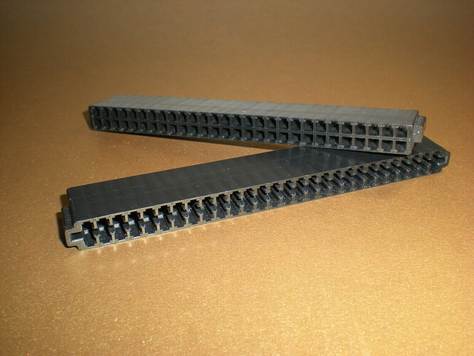
  2. I don’t have that blue type of JAMMA harness. Mine is like the black one in the pic here:

And some of the “holes” have no wires running to them, and you can tell from the side that plugs onto the PCB because there are no metal “teeth”. So there is something that creates the “teeth” that crimps onto a wire. You can just add more into there somehow. That is what I am asking.

  1. The part names for the Kick Harness are listed at the bottom of the page I linked you to.

  2. Interesting. I’ve never used “empty” JAMMA harnesses like that before. All of mine were the blue kind with all the pins/teeth already in, and you solder directly to it.

The part I am talking about that is in the picture I posted above is not listed there. It is some type of connector but I don’t know the name of it.

Ah. You’re asking about your “custom” connector, not a standard Kick Harness.
Sorry, not sure what that is.

There is no standard kick harness. What you are talking about is specific to CPS2 and it has like 34 pins on it. I’m asking about what is specific to my cabinet. Those are just generic connectors though as they are all over arcade cabinets.

All a kick harness is a way to wire up the extra 3 buttons for games that require 6 buttons.

jesus! stop calling it kick harness it’s confusing. It seems like your cabinet is not standard jamma if you need more wires just get another complete jamma harness to replace it from ebay make sure it’s standard jamma harness as there’s also this chamma variation that has a different pin out those are used for pandora’s boxes I think or that maybe be what you need look it up.

also if you need electronic components, connectors and the like you need to get them online from websites like https://www.mouser.com/.

i don’t have an answer to your question since i’m also a beginner on this arcade stuff but i can link you to a webpage where they can help you with this and your broken KI motherboard,https://www.arcade-projects.com/forums/

You guys need to educate yourselves before talking about things you don’t know. It is called a kick harness and my cabinet is a standard JAMMA cabinet that is used for fighting games.

JAMMA has 3 buttons wired by default on pints 22-24. The extra 3 buttons are typically added for fighting games on what is called a “kick harness” and it’s completely separate from the JAMMA harness. It’s it’s own little harness that goes directly from the control panel to the PCB at another connector location.

Different games have different pinouts for this connector on the PCB. The pinout for the 6 buttons is always the same on my control panel, so that part of the kick harness is always the same. However, the part that connects to the PCBS vary. Like the pinout on KI1 and KI2 for buttons 4-6 are the same, so I can use the standard kick harness that is wired into my cabinet already and it works fine. But MK1 and MK2 have different pinouts for buttons 4 and 5 (LP, LK) so I need different kick harnesses for them.

MK1 kick harness - Mortal Kombat Extra Buttons Auxiliary Kick Harness Arcade Adapter | eBay

MK2 kick harness - Mortal Kombat 2 Extra Buttons Auxiliary Kick Harness Jamma+ Low Punch Arcade | eBay

Here is a pinout of the MK1 PCB. The J4 connector is where the kick harness connects to:

Here is the pinout of the MK2 PCB. The P5 connector is where the kick harness connects to:

As you can see, the LP and LK pin placements are different therefore you need different connectors, ie kick harnesses.

There, now you all have been educated and hopefully don’t spew crap next time you think you know WTF you are talking about.

Dude, no need to get offensive and condescending. Most of us are just trying to help here.
When I started to get into arcade stuff many years ago, I was told (and I unfortunately don’t have any sources on this) was that the wiring to get additional buttons was called a “Kick” harness because Capcom put their 3 kicks on it, so the general understanding was that “Kick harness” referred to Capcom’s “CPS2/CPS3/Naomi-compatible Kick Harness”.

Anyways. With that out of the way.

That being said, I’m still trying to help out here.
Can you take some additional pics of your harness? Still can’t figure out what it is. Some Googling says that’s a standard Molex connector should work, but the pin count doesn’t match up between what I’m reading and what I’m seeing in your pic. Is there only one row of connectors or is it double-sided?

Yeah my bad, it just got annoying hearing you guys be wrong lol. So I wanted to just clarify. Sorry i did it in a kinda dick way.

I actually ended up ordering some parts and they are coming today. My pi2jamma came and I’m actually going to work on a harness for that today. I took some measurements and stuff and am pretty sure that I need some kind of .100" pin connector. I ended up getting this:

https://www.marcospecialties.com/control/keywordsearch?SEARCH_STRING=CF10012

I then got some .100" pins to put in there:

https://www.marcospecialties.com/pinball-parts/CT100S

I wanted to get an 11 position connector but they didn’t have any so I just got a 12. In the end it doesn’t really matter, it just won’t look as clean lol, but hey what can I do. I did get a key to put in one hole though since the male connector it goes on has a key, so that way i won’t be able to put it on wrong.

So the way pi2jamma works is that it has buttons 4 and 5 wired into pints 25 and 26 on the JAMMA harness. So I also got the crimp pins that will go into those empty slots on my JAMMA harness, and then I will wire those 4 wires (2 for each player) to the corresponding pin on that connector up above. Then buttons 6 go to screw terminals on the pi2jamma, so I will wire those up to the spots on the connector as well. I plan to use zip ties and stuff to wire it along the JAMMA wires in the cabinet so it’s clean.

These are the JAMMA pins I got to add the extra connections to the harness:

https://www.marcospecialties.com/pinball-parts/08-03-0304

Then once I have all of that done, I can use all 6 buttons on MAME.

I think the actual connector that I took a picture of though is called an IDC connector. I think it is the .100 size and not the .156 size as in the link below. It looks identical to the one I have.

https://www.pinballlife.com/mm5/merchant.mvc?Screen=PROD&Product_Code=idc11-22

I opted now to get those though because you needed some tool to get the wires down in there, and they just kind of “press” down there. I have connectors like that for my current MK1 and MK2 kick harnesses and I don’t like the connection it makes, so I think crimping to pins and putting into the molex connector will be a better solution. And that is as long as it fits, but I’m pretty confident it will. I’m going to be annoyed as shit if it doesn’t fit though since my plan is to do all this work today lol.

Yeah through-out the years i’ve heard the term “kick harnass” and had no idea what it meant. It’s simply the extra 3 buttons required for fighting games, specifically the 3 kicks. Which is why it’s referred to as a “kick” harnass.

Prior to the 6-button fighting game craze, majority of Arcade games only had 3 action buttons max. This all changed when Street Fighter II hit the scene.

1 Like

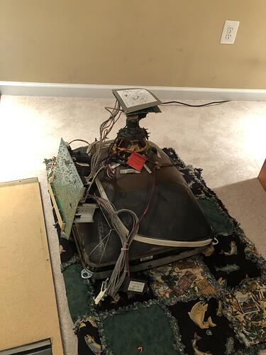
I’m actually heading to Buffet’s house tomorrow with my monitor and tube and hopefully he can rejuvenate it. Had to remove it again but it was much easier since I knew WTF I was doing lol.

1 Like

I just finished my jamma pandoras box 6 and yes u have to add wires to btn5 and btn6 on parts and solder side of the jamma harness. I belive most harness have btn4 pre wired in. Hook your btn5 & btn6 wires and dasiy chained grounds to your microswitches and that should do it.

1 Like

I got it figured out a couple weeks ago already. I made a long post with pics about it in the GD VG thread since they were interested.

I ended up making my own “kick harness” basically and made it all clean and pretty. Then mounted the pi2jamma to my cabinet. I have since added some 1" spacers because I couldn’t get the SD card out while mounted.

1 Like

Just got back from like 3 hours at Buffet’s house. That dude knows his shit man. He reflowed my neck board and chassis and then recapped it too. He also replaced some resistors. He ran a test on my tube and didn’t run the rejuvenation stuff because it all tested in the green.

And damn everything looked super bright and vivid after we tested it out. We let it run for like 40 minutes and it was fine and he calibrated it and showed me how to do it and said it will have to be done for each game.

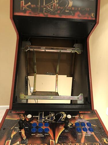
My dumbass though didn’t bring it in the frame. I didn’t even realize that was a thing. Had I done that it would have been so much easier to transport and keep together. I’m going to take my frame out tomorrow and mount it to that, then put the whole thing back in because it’s just easier to put everything on the frame outside.

I wish I wasn’t such a noob about it lol. He had a frame we mounted it to and stuff but it would have just made life easier for us had I brought it in the frame. And would have made taking it in/out of my cabinet so much easier.