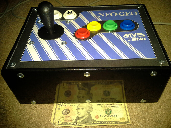
Building Neo-Geo stick for MVS console

I am in the process of waiting for an MVS system to “consoleize”. I have not decided yet if I will do the work myself and save some money, or just buy a pre-built. I have decided on building my own stick because the prices for a used Neo-geo stick are outrageous, and they don’t have the same look as the arcade style. Black is classy, but there is nothing as cool as the multi-color setup of Red/yellow/green/blue on a red/white background.

This is going to be a 4 button + Coin/Start with the basic color scheme of the MVS arcade. I will be doing all of the lumber work myself. I plan on a basic deep red stain for all of the wood, and will be doing the “detail” work of the black & white on the inside of the lexan top.

I have a whole pile of sticks and buttons en-route to my house, as well as Neo-Geo extension cables. I plan on using a db15 breakout box mounted inside of the stick but mounted flush with the back so that I can plug and unplug the cables when they are not in use.

I have no intent of ever using these sticks for other systems, so 6 buttons and additional electronics are not needed.

Things I am sure I don’t know:

I have not decided on dimensions yet. One potential is that when I buy the materials, I just build based around the size of lexan that is being sold. I hate cutting lexan. It never ends up being perfectly straight. I hate drilling lexan as well. I have made many things with lexan including water-blocks for cpu cooling. I may skip the plexiglass entirely. I can always put a very very thick layer of polyurethane and be content with its protective qualities.

Any suggestions from others in the Neo-geo family of DIY enthusiasts?

Edit
I broke down, and ordered a pre-modded MVS console and the 161 in 1 game cart. The cost was not cheap however reasonable for what it is. I really don’t think I could have done it much cheaper based on how I value my time.
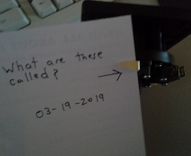
OK. I have my first question. I included a photo. I am looking for a spade style quick connect. However, since I am not an electrician, and there are many various sizes, how would I measure this to know which size would work best? The width of the connection of of the switches is exactly 5mm or very close to 3/16". Would I be looking for the 4.8mm female spade connectors?

You would be looking for 0.187" quick disconnects.

1 Like

Many thanks my friend! I am starting to get really excited about this project. I am still torn between ordering an MVS overlay for the control panel, and just building from there, or doing something custom. Having the buttons is really setting a fire to get this project moving.

Yup, we’ve all been there. :slight_smile:
It’s nice to have most of your parts so that you can make some progress on the project while you wait to acquire other parts.

As you’re doing already, feel free to document your work and progress here, and most of us here will usually provide feedback or advice if you need any.

2 Likes

I am active in a few hobby specific forums, and I always give as much back in photos and descriptions…but also know that I somehow get more out of the sites than I can ever give back. I may be new here, but I do have a strong belief in community…no matter what the community specifics are. I am a very big supporter of DIY, and know that simple contributions can make a huge impact in other’s decision making process.

1 Like

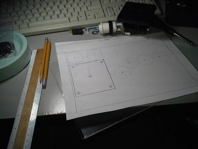
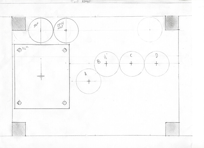
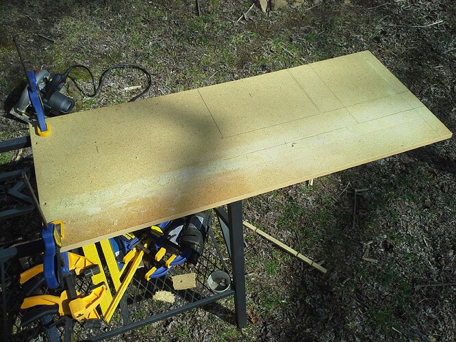
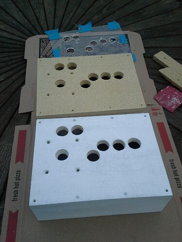
Did some shopping today, and picked up most of what I was missing. Amazingly enough this local hardware store cut my acrylic for free. I can handle that. I spent the evening doodling various designs as I sipped on my Doctor Pepper Cherry. I ended up with a 8-1/2" x 11" lexan topper, and will be cutting some leftover MDF tommorrow. The walls are 3/4" thick “1x4” pine. Once I get it together, I will be cladding the outside with 1/4" red oak…but that is getting ahead of myself.

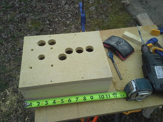
I am going with “Plan B”, which I scanned for a template.

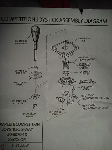
I do have ONE question about SuzoHapp Sticks. It has a piece in the instructions called the “Cylinder” which goes above the hub. However, why couldn’t I put it below the hub on top of the actuator? Is this a method to reduce the height of the stick?

Worst case scenario, I waste time. I am going to be putting this together tomorrow, or at least trying.

I still don’t have the DB15 cables or the breakout box, so I will quickly make 2 control sticks, and be bored of looking at them. That will teach me to order things from China.

It’s been a while since I’ve assembled a Happ Competition stick, but I believe the cylinder is needed (as per the instructions) if you’re mounting it on a thick (ie, wood) top-panel. If you’re mounting it on a thin (ie, metal) top-panel, you remove the cylinder entirely, and you connect the e-clip/e-ring onto the higher notch.

Don’t put the cylinder under the hub and over the actuator. Things won’t line up that way.

1 Like

The actuator fits right where it belongs, and the cylinder would then go “on top” of it. The c-clip still fits in the same spot. I will most likely mount as per the instructions, but was just looking at how the stick itself has 3x spots that the c-clip would fit all of them. I budgeted space for a stick, and this may work for a deeper build or a cab. its a 3/8" difference overall.

Oh, I misunderstood where you were planning on putting the cylinder.
I wouldn’t bother to put it elsewhere; either use it where the instructions show it, or just avoid any headaches and remove it entirely.

1 Like

Instructions suggest that this unit is for 3/4" plywood control panel with plexiglass. After getting these half done today, I realize that that cylinder is 100% essential for this depth of panel.

My top panel is 5/8" MDF that was a left over panel from my kids toddler bed 10-12 years ago.

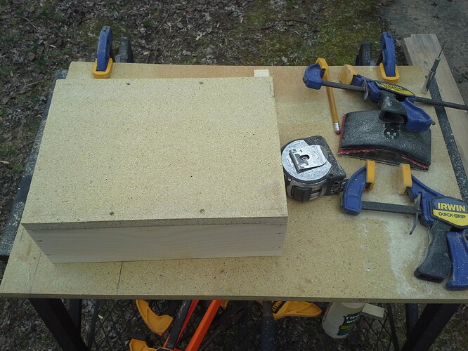
The sidewalls are held up with 1x4 pine which is actually 3/4" x 3-1/2".

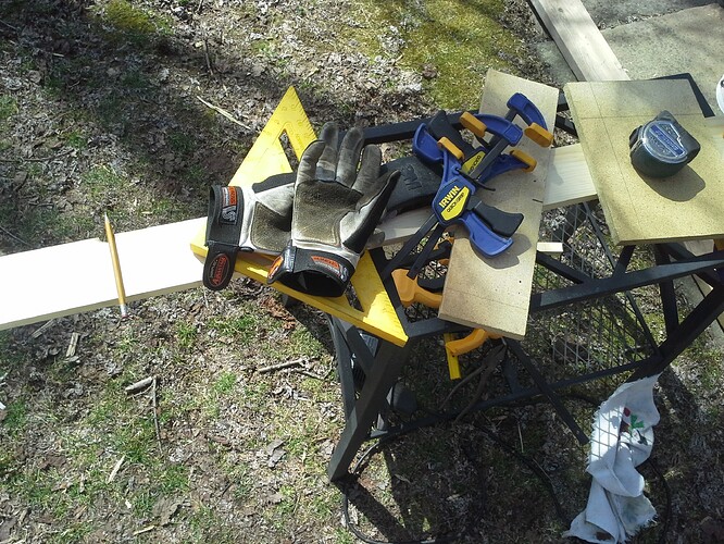
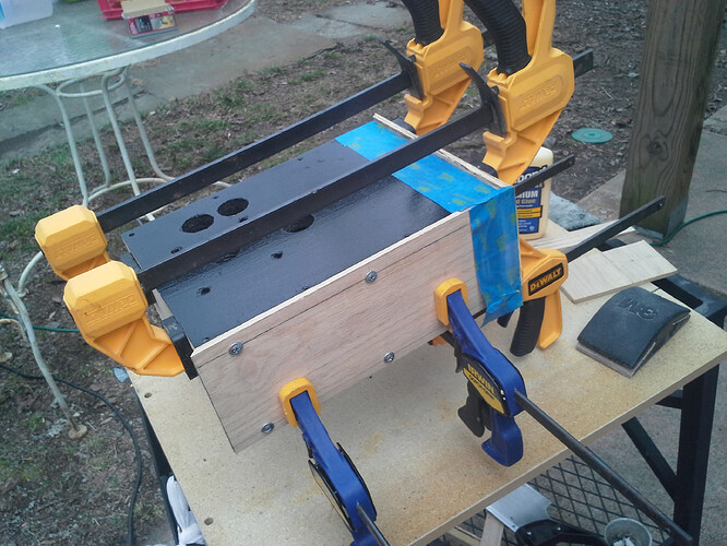
I glued it all together and clamped it while I drilled some small decking screws. I used Titebond III. Everything was sanded over and over by hand. I wish I could say that tommorrow is leg day, but its not.

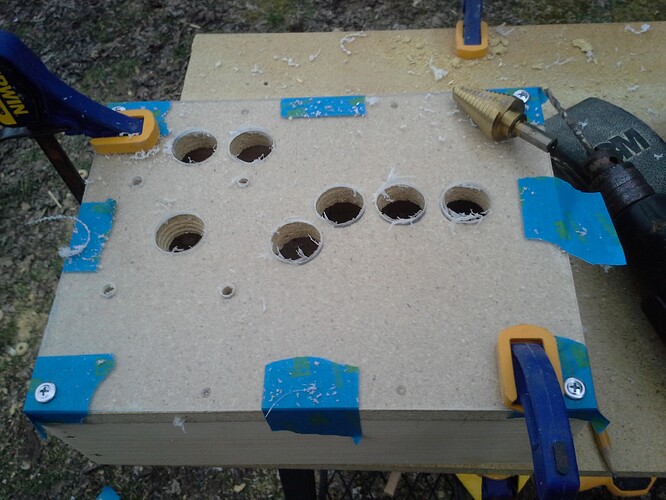
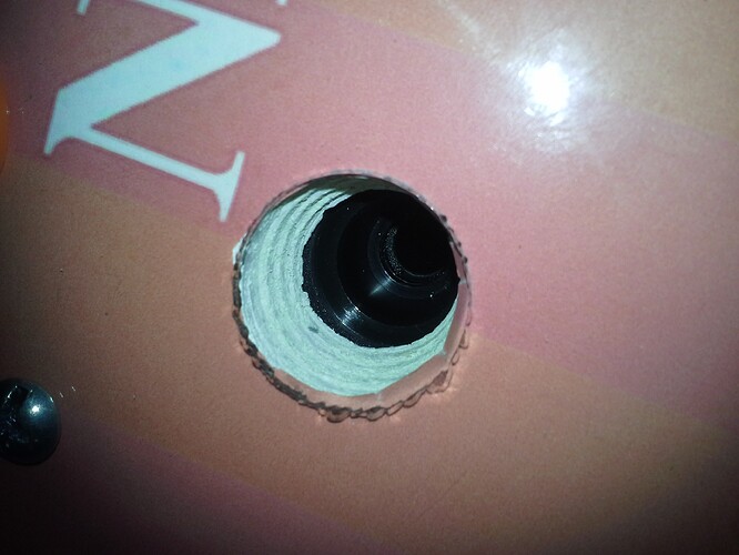
I drilled out per my previous post’s exact template with a 1-1/8" spade bit except on the stick hole. That was done in 7/8", and beveled out with a stepdown bit. The top of the hole is 1-1/8", whereas the bottom is 7/8". I could have/should have done them both in 1-1/8" from the start, but that was my 1st mistake of the day.

The plexiglass was done with an acrylic bit for a pilot, and bored out with a stepdown bit. I cracked one slightly, and it will be redone. As many times as I worked with plex/lexan, I am somewhat impressed that I only broke one hole. Sure the whole thing is shot, but out of 14 holes, only having one fail is exceptional…for me.

I forgot what I was doing and put primer on one of these. This was mistake #2.

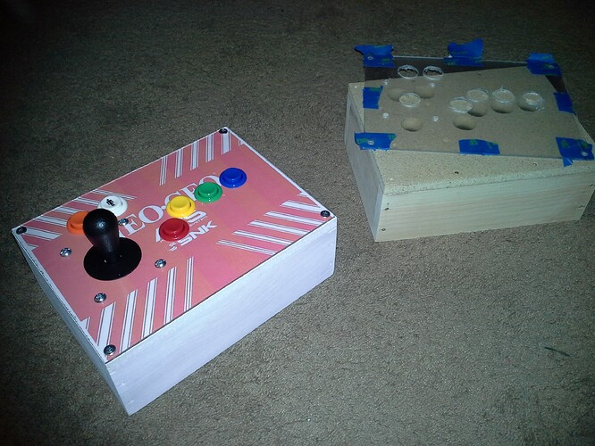
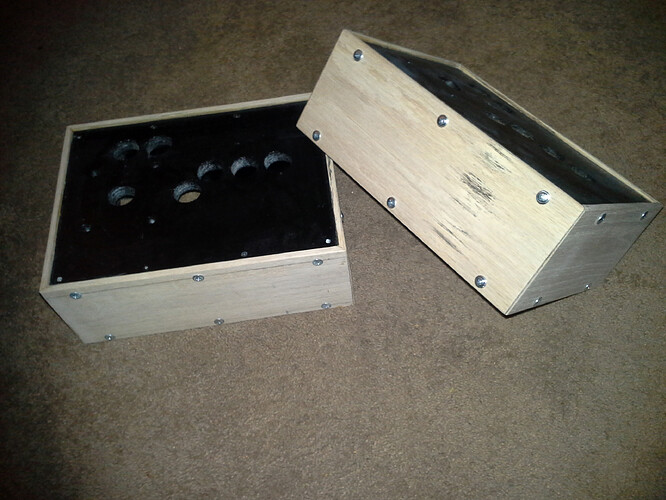
This picture is a test fit. It is tight. I will be mounting a board into the bottom next weekend. I don’t want to increase the height any more than the 4-1/4" overall that I have now. The sides will be covered with a black-stained 1/4" oak trim. Also, I am going to print images that aren’t “econo print”. I haven’t decided on an image, but I think I may use photoshop and my template to make something customized to the layout.

This picture shows what the control stick hole looks like.

Edited
added missing photo, and did some grammatical clean up.

Still waiting on the db15 female breakout box, and the Neo-geo extension cable. From the way it looks, they could be weeks away. In the meantime, I spent a few more dollars and ordered a 10’ db15 MxF & another breakout box from a seller on my continent.

In the meantime, I was going to take a few days to do the wiring, but ended up doing it all today in my spare time…In between cleaning up an acre of yard, and chainsawing tree down to 24" sections.

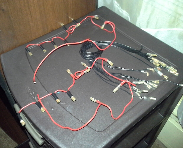
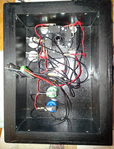
I am not an electrician. I don’t even try to fake it. The red wire is for the ground. It was leftover from a ballast replacement on a shop light. It is thick, solid, and holds its shape. I think it is rated to 120v. It reminds me of tubing bending. The black wires are for each button, and is a thinner gauge copper. I did both ends on the button wires, and will be cutting off exactly what I need when I need it. I soldered every single quick connect, and ran a probe across the ground wire to check for continuity.

Tomorrow I am going to get the oak for covering, though I haven’t decided on just regular flat pieces or some sort of fancy molding.

Pretty soon I am going to be bored, and waiting for my connectors.

While I waited I did some graphics for the top. I pulled inspiration from a few panels both official MVS and some of the custom made units that are out there. Every part of the graphic had to be made by hand including the stripes. It still isn’t perfect, and I think I will make one more alteration. The start button vs the coin button. Too much black on the left side the start vs the right of the coin.

Still waiting on multiple sets of DB15 wires, DB15 connectors/breakout boxes and just in case a set of Neo Geo extension cables. I am also having trouble finding the proper quanity/cost for Indian ink for treatment of the finishing wood. I may have to order that online also. I will know more tonight. I sure as hell am not paying $9 for 2-4 oz of ink, knowing that I would possibly need more…not when I can order a quart for slightly more over the internet.

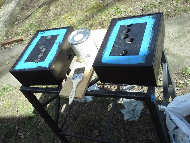
I painted the top of these black with an automotive finish that I had laying around a 2 days ago. There is a very small edge around some sides of the graphic, and this will cover it up. I also did the inside of the boxes because I have no use for automotive spray paint, so I might as well use it up.

Today I spent a lot of time on 1/4" oak. Pieces were more than wide enough, and I had to cut strips off one side. I am no carpenter, and only have a circular saw. If I had a miter saw or other gadget, this would have been done and I would have been bored with the rest of my day, but I did enjoy the struggle. I used the circular saw for my 45 degree cuts, and a hand saw for the straight ones. I am one of those sick bastards that prefers to use a hand saw, and have made some really nice things in the past. With all the setup and measuring setbacks etc with a circular saw, It saves time for me to just make a mark or 2, and rip into it with a good handsaw.

My plan for today was to cut, sand-prep and glue & screw every panel. Everything was covered in Either tightbond formula 2 or 3, depending on the unit. I had some of each, and never did a side by side. The blue controller is type 3, the red one is type 2. I honestly think I prefer the #3. It seems to dry a bit slower, but also seem to be somewhat clear. Also it is water proof, vs the #2, which is just resistant.

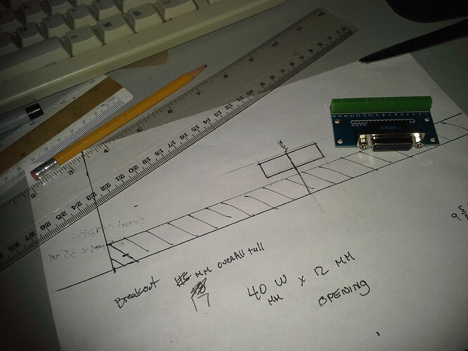
After I budgeted a plan, the mailwoman delivered some goodies. One package was the db15 breakout box. Another was AES extension cables…The rest of the mail was bills. Either way I was busy most of the day with fighting with my inability to be a carpenter, and didn’t have time to budget to plan for electrical. I already knew where I wanted it, and tonight after dark I set down and found out that it will fit exactly where I want it…Centered in the back of the controller, near the bottom. It is getting mounted to the bottom panel, and there will be a small cutout for a db15 to attach to. Bad news is that the AES extension doesn’t work with the DB15 plugs, and I don’t feel like modifying a wire quite yet. It has a different depth for the plug, and if I have one type, I might as well stick with it. Db15 from this point out.

I didn’t get to bore out the hole for the wire/breakout, so I didn’t stain. I didn’t get to finish sanding either, and there is a bit more detail work. I need to find something in my house that is 1/8" wide I can use as a sanding guide for the oak. The plexi fits really nice as it is, but there is some fine tuning that needs to be done.

I got some stain that the guy at the local hardware store swears will be ebony black. He told me he personally used it for some chairs at his own house. I am looking forward to sucking in stain fumes tomorrow.

1 Like

Paining the top panels is a good move, specially if the graphics do not have 100% full cover.
Also the Paint can act as a immediate layer for adhesive if your graphic has any.
And if not you just sealed the wood fibers up, which is also a good move.

1 Like

This was my main goal, however I knew I would end up painting. My graphic is just slightly smaller than the size of the top, so there would be a visible line around the thickness of a sheet of paper. I painted it now to make any glue or stain spots an easy cleanup. It worked out well. I do need to put one more coat of paint on the top. It did get scratched up from all the work I did.

The boxes are pretty much done. I have one bit of detail work yet to do, and this is a HUGE mistake on my end. I did cutouts for the internal DB15 board, and they look great for my method. However, it looks like the cables I will be getting have larger plugs than the breakout box. I figured this out after I cut them out. It won’t be that much extra effort, but It isn’t that big a deal.

I also don’t like the look the stain left. It reminds me more of a paint than a stain, and I may sand and refinish, but I doubt it. I am just about done. I will check it out tomorrow after the stain dries and see if I care enough to change it. For anyone thinking about “ebonizing” oak, india ink is the best option every time. I have tried dark stains many times over the years, and nothing does black while still preserving the look of the wood.

1 Like

I sanded the whole thing down with 220 grit wet sandpaper until I started to see the brown of the raised grains. It created a very nice “aged” effect. It also exposed the grains, and I used a 50/50 mix of India ink and water to cover over it.

India ink is some powerful stuff. I have never worked with it before, but it is BLACK. Even at a 50% dilution it is black, and absorbed into the exposed grains quite readily. I don’t dare sand any more, as I don’t want to destroy the oak grain/texture, and if I feel the need to sand, I will be going back to a 60-120 grit to bring it all back to square one. I am very very particular about color and texture of wood. I have redone many pieces over the years, and I certainly take more time than is necessary but I think the added attention really puts things over the top. I gave all my friends custom refinished “coffee” tables when they got married. I know what kind of slobs my friends are, so I always made sure to make them water proof. Another thing I like to do is after 6+ layers of polyurethane clear coat, I use 2000 grit wet sandpaper to put a mirror finish on the clearcoat. It is an identical process that one would use for automotive finish. after it dries, I ALWAYS use a good coat of “McGuires cleaner wax”. For indoor purposes, this wax should last 10 years or more. You can toss a playing card on any of the tables I have done and watch it drift from one side to the other before it falls off. It is a beautiful thing.

I am waiting to clear coat now, and am at a standstill. I NEED the db15 cable so I know if I have to enlarge the port on the sticks…My guess is that it is a guarantee. How big is information I am missing.

Progress has been made, and for the most part these are complete (Will save that for another post). I received the 10’ db15 cables, and as suspected, they are bigger on both dimensions, so I had to enlarge my access port on the back of the unit. Another “incident” was my last coat of clear coat and a bug on one of the units…the bug really got into it and messed it up. My method of finish on these is smooth. I did these no different than I would do a tabletop. I wanted mirror finish irrelevant of the wood texture. This gives a nice effect of a mirror finish, but the depth of seeing the wood. The black stain reduce the effect of the wood, so in essence it is nearly a piano black. I am still waiting on one side to dry on one of my units, whereas the other one is complete, and working…and its awesome feeling. That bug really messed it up. In a way I am glad it killed him/her.

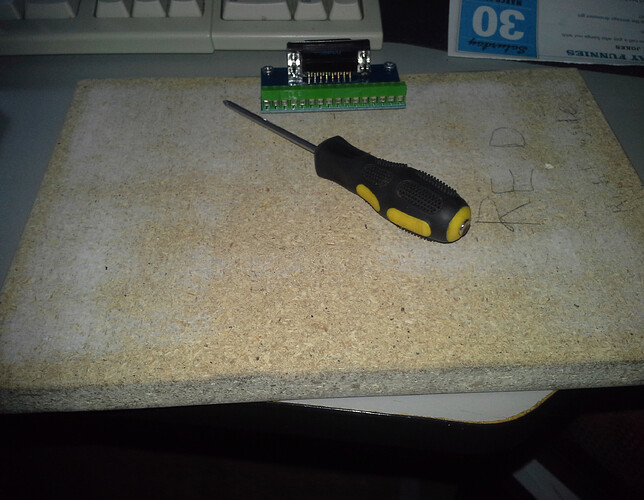
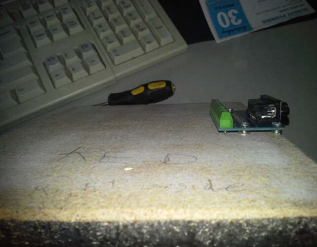
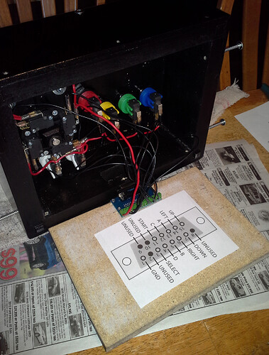
My bottom with the DB15 breakout mounted. I used aquarium airline hosing as a sort of bushing between the board and the bottom of the PCB. It worked out better then expected, and I would use this trick again. The bottoms fit right up inside of the unit. After I did the math, I found that I had less than 3/8" total clearance inside. I don’t think I could have made this any smaller with the Happ hardware.


Wires were easy and finding a proper pinout was also really simple. I am glad I used a DB15 breakout instead of doing each wire individually with solder.


The next time I post, I expect it to be the final unveiling.

Finished:

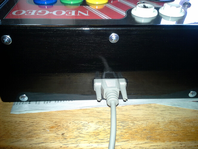
This is the way the db15 cable attaches to the breakout box inside the shell. They come off cleanly, and insert without issue. It took some tweaking, but was well worth it.


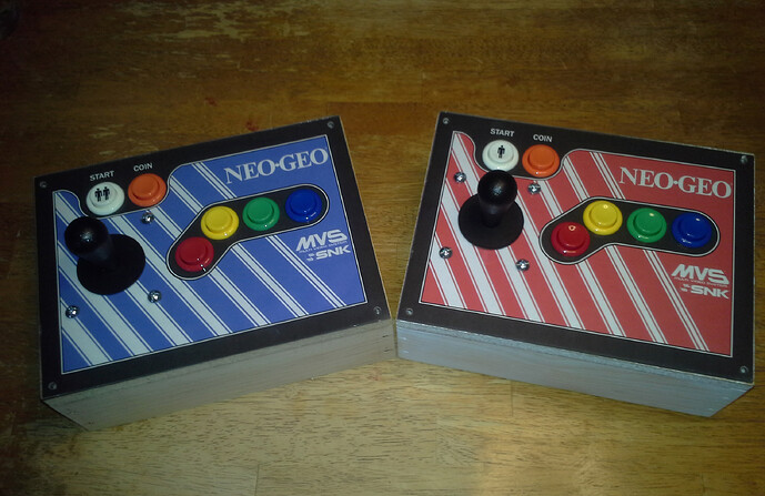
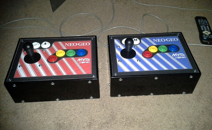
They came out really really nice. Nicer than I expected, but with some issues, but this is normal for handmade things. Nothing is ever really truly perfect. However, the finish is GLOSSY. I have never done anything of this degree of gloss, and usually stick with satin or even flat finish. It is so damn hard to capture the “look” of this on camera. There is real depth of wood under the clear finish. The best picture showing this effect is the one above with the db15. Both units look like this. I don’t know what you would call it. It is not piano black, but something else.

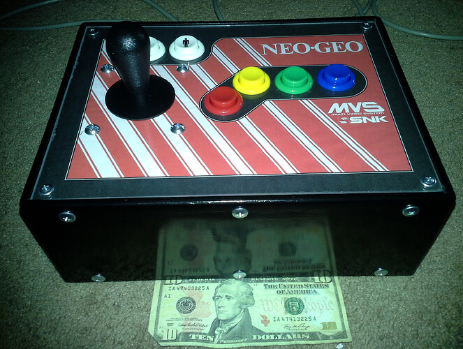
I used a $10 bill to really highlight how reflective these really are. The coat of automotive wax really was a nice touch. They are downright slippery, and will be for a few months.


The graphic took a few hours in photoshop, most of which was tossed out over better versions. Everything but the Neo-Geo/Aes/SNK logo were made from scratch. I did not use any letters at all on the graphic. I wanted it plain. I thought about lettering the buttons and the start & coin, but after a few tests It just looked cluttered. I wish I had a better printer that worked on photo paper, and that is something that we are in talks about. Not that I am going to take this all apart just to put a shiny remade background…

I can’t wait to try these out. Aside from a brief test, the kids have been on these the last hour. Ill have my chance after they go to bed.

Overall, I would not recommend this sort of project to someone who did not have a supply of tools. I had most of the hardware needed to make these. I wish I had more, and this would have been done quicker. I keep meaning to get some sort of radial arm saw, but I got no room for it at the moment. I know I am redoing my bathroom in a few weeks, and I may be able to justify it then. All of my painting was done outside. This was a very easy project overall. I could have done a 6-8 button, but I have no need for USB.

HOLY COW are they heavy. I think you could park a car on these and have no issue. After it is all said and done, the sidewalls are all 1" thick. The top and bottom are only 5/8".

If anyone is interested in my photoshop layout, or anything else specific to this, don’t feel afraid to ask.

1 Like