@charchi
If it has a interrupt on V3.15, you must to upgrade it.
adding a breakout board won’t introduce lag as there aren’t additional controllers messing with the data flow
@GOGO.Zippy check the inbox
@gahrling @Darksakul @aszyd
well, guys, i have to admit, that this soldering may not look very perfect, but it is sufficient. PCB was working for some time, so soldering is ok, pcb wasnt thrown, pcb and wires were not affected with destroying power or something like that. It was working, then after 2-3 hours of rest with no forces affecting it, it stopped working. So, really, is there any chance, that solder disappeared from some spots making pcb not-working? think not
@Darksakul so, de-soldering is still possible? u advice me to completely de-solder it, then solder USB-wire in a more proper way and to check PCB for workability?
Just add more solder to the underside where you took that pic, make the whole pad covered in solder so it looks like a silver blob with a silver wire coming through it.
@Capablanca
Please look again.
Red/white/green/black wires of USB Cable solder on correct J1’s holes (VDD/D-/D+/GND) on P3/P4 Fighting Board.
Did you watched any of the videos I provided?
@Darksakul: Those are great videos! I especially liked the first and third. Short, succinct and covered a lot of ground at the same time.
@Capablanca: The whole thing needs to be redone, but for the purposes of troubleshooting re-solder the USB connections first (and watch the videos before you do). Also, you have solder on every pad, do you have a wire connected to every pad as well? That is not necessary and probably not recommended. There are a few pads that aren’t used and several that would only be used in an advanced install (LEDs, turbo, touchpad, etc).
http://www.brookaccessory.com/detail/58690501/#cont2
Can you provide a photo of the other side of the board so we could check for shorts or other potential problems?
Hey guys, does this PCB support an SOCD Cleaner or does it have one built in like the new universal PCB?
Great videos here.
@Capablanca keep practicing. Better to get it done right while board is out. It really sucks having to disassemble a stick just to trouble shoot a problem on initial use.
while it may not have an socd cleaner, it’s something brook can incorporate via firmware update
Right, for people that want to make a hitbox or install into one.
SOCD was designed mainly for hitbox, so they can’t block in both directions at the same time and make it easier to jump from a crouch. If they are installing your board in a hitbox or if they are building their own, they will need SOCD.
Does your board support SOCD?
Yes, i Did
and here is the result, we`ve made some improvements
we slightly resoldered pcb
checked usb multiple times, even tried another one usb-wire
everything WAS cheked with multimeter from the very beginning
and no working still
What do you mean by “slightly resoldered”?
You should atleast completely remove solder from the usb points and resolder those from scratch. Also id solder the usb wire directly to the pcb rather then using a pin header, atleast until youve gotten it working reliably
Your D+ still looks like it’s barely hanging on but if a new cable and a multimeter say otherwise, it could be the voltage regulator.
check voltage on J5 pin 1 or U3, should be 3.3v
if it’s lower than that you need to replace
dont quite understand what do u mean. Where is j5 pin?
and how to measure voltage there?
Please look this link http://www.brookaccessory.com/Archive/_eng/upload/BFEN2.PNG
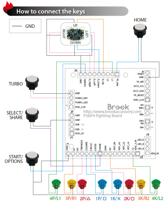
Please use multi-meter to measure.
VDD_5V connects with usb cable
VDD_3.3V outputs from a LDO IC.
They are two different voltages, please don’t short together.