Hello, I have bought the Brook PS4 + Audio Fighting board. I have modded my arcade panel to add an analog stick.
The problem is that my controls are inverted (up/down). No matter how I switch the connectors, there is always one axis (either up/down or left/right) that is reversed while the other axis is correct.
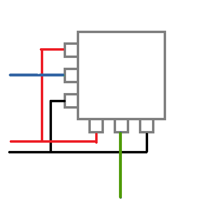
I have analyzed the assembly diagram on the Brook site (and the manual) and I have noticed that the pins on the diagram are inverted too, see the pin #1 :
here
and there
I don’t really trust the schema anymore and I wanted to know if anyone knew how to connect analog PS4 sticks?
I’m very disappointed with Brook, it’s not the only problem I have with this product and even though I’ve finally been able to find a solution to my previous concerns, I’ve been stuck on this part for quite some time. I have tried to contact the support but they don’t send the confirmation email (I have tried many mail providers).
Could you please help me with the pin layout both on the sticks and the PCB ? Thank you very much.
Take clear pictures of your wiring.
Sounds like the variable resistors on your setup are possibly not set up the same way as the drawing in the Brook diagram.
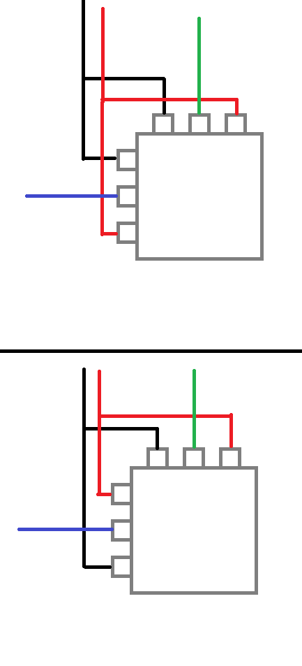
See my crude MS Paint diagram:
Their diagram is like the top image. Notice how the black and the red wires are connected.
Your setup is likely like the bottom image. Notice the black and red wires are offset from the image in the Brooks documentation.
If you’re grounding the black wire and putting Vcc to the red, your Left-Right will be fine, but your Up-Down will be reversed.
If you’re putting Vcc to the black and Ground on the red, your Up-Down will be fine, but your Left-Right will be reverse.
Two ways to deal with this: either isolate the Black/Red connections so you wire them up separately (not sure if this is possible due to not knowing how your analog module is set up); or even easier (if this is possible in your setup)., rotate the entire module 90 degrees counter-clockwise, and reverse your wiper/signal wires (ie, instead of Blue = U/D and Green = L/R, use Blue = L/R and Green = U/D).
3 Likes
Thank you very much, I think solution #2 is the only possible one due to tha fact I have only 1 GND and 1 VCC pins on the PCB.
Before to start the fix, I hope to come back with a diagram just to be sure I have well understood.
Thank you very much again
Hello, I have finished the drawing, please, could you confirm we have the same understanding if I do the method #2 ? :

Thank you very much !
Yes.
Because if you look at it this way, both the right contact of the L/R potentiometer and the bottom contact of the U/D potentiometer are linked, just like in Brook’s image.
Likewise, the top contact and the left contact are linked.
You’ll probably need to run GND to the top-and-left contact, and run VCC to the right-and-bottom-contact.
1 Like
Sorry for my late reply : I juste have finished to solder everything and I confirm that it works !
I thank you SO much for your kind help !!!

