I’ve got a arcade stick I made from scratch last year for my ps1/2 using the solderless method that I’m in the process of adding a pad hacked Xbox 360 wireless pad (common ground one) to that I need help with.
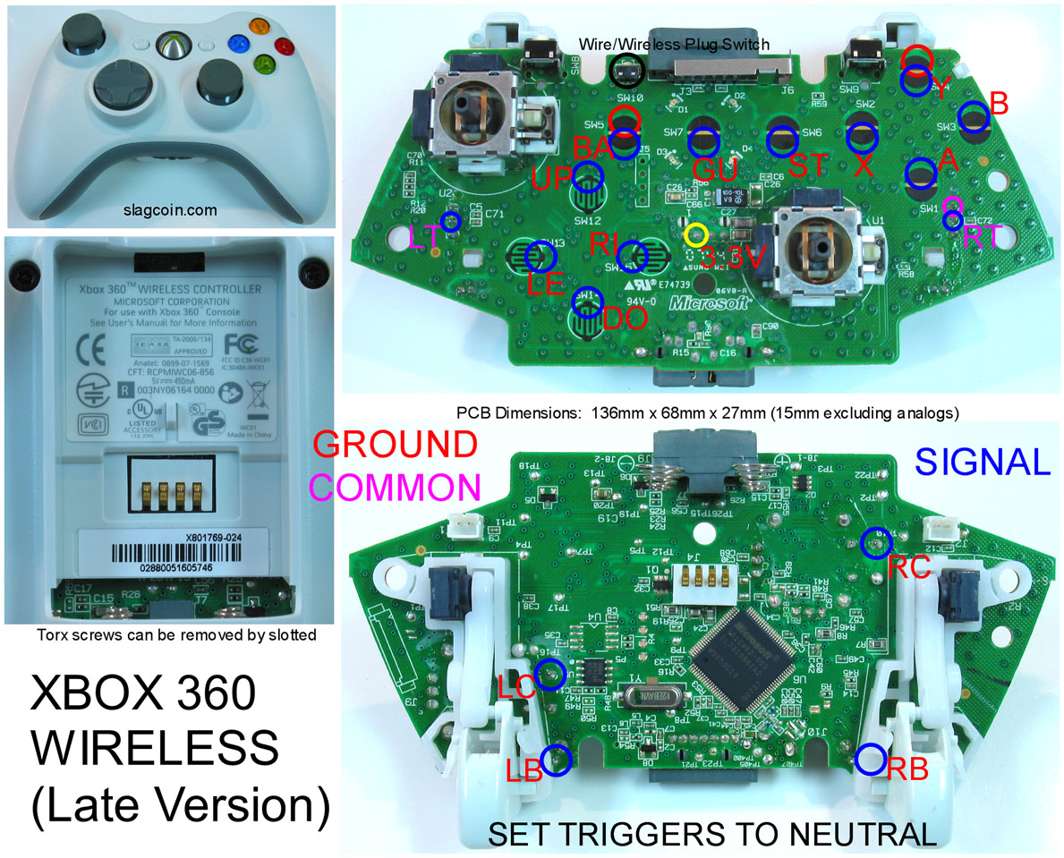
I’m using the slagcoin diagram for doing it.
Have a couple questions I ain’t been able to get definitive awnsers to.
I had problems soldering to the right dpad button, I’ve read that I can solder to the via hole but some people sat I need to scrape out the hole and poke a wire through and some say don’t scrape the side coz it will break it. What is right?
I’m a bit confused with the ground situation on the common ground pads. My arcade buttons grounds and sticks grounds are daisy chained. I’m unsure were I need to connect it to the pad. And is there just one ground or a couple?
I want to wire up the triggers to arcade buttons, I’ve removed the triggers from the PCB and left with the 3 holes but not 100% sure of how to wire them.
Their is a Wireless common ground Xbox 360 pad? I doubt that is right.
The Wireless pads are not ideal for dual mods, the best pad for a dual mod is the wired Mad Catz Fightpads
What?!
Golden rule on Dual Mods. ALL Boards need power, ALL boards need ground
For your buttons and joystick, as long at your PCBs are common ground, you only need 1 ground wire going to each PCB
Dual PCB mod controller is easy, each PCB is wired to a d25 male connector and the arcade buttons/stick are wired to a d25 female connector they all plunged into a little switch that’s readily avalible online and you just have a little button were ever you want on your box that selects what PCB you want to use.
The link you gave is only good for a certain model of pad that isn’t the one I’m using. So still need info on making triggers work for a late version ms Xbox 360 wireless pad.
Again ill explain question 1).
The contact for right dpad is knackered so you follow its trace and you fined a via. My question was how to solder to the via as I’ve read conflinting information.
Actually that isn’t a common ground pad, there a common and there a ground but the two are not the same thing.
Are you 110% certain that your PCB in that diagram? You might want to get a multi-meter and reconfirm what Slag coin showing you.
It would be the same kind of hack.
You follow the trace till you find another point to solder too, if it is a chip you solder directly to the correct leg of the chip.
I followed the trace to the via, for soldering to the via do I scrape the top of it or inside it? Being a weak joint ain’t a problem, that’s what hot glue is for lol
Yes that is the pcb I’m doing. It’s the closest to a common ground and is referred to as the common ground one all over the web that’s why I refer to it as the common ground one.
At this moment in time I don’t want to spend out on any other pads, its possible to do it with this pad from what I’ve seen so I’d like to do it with this one.
I’ve searched the net and figured out soldering the ground, but its just how to solder to a via I need to know as I’ve never soldered to one.
The late version models are common ground. All of the new chrome ones are as well. The common in the diagram is for the triggers. They are active high signals. The common is a voltage source that the triggers share to raise the signals to a high state when pressed. Though you are still correct about the trigger hack being the same.
Scrape away the silk screening on top of the via. Solder to the top of the via. Best to use 30 gauge wire.
What? No. Prob read that from the Xbox One padhack thread.
Keeping it wireless, I’m sure the resister thing was for a ms 360 pad. It says that works a fair few times in different posts on arcadecontrols forums.
Basicly my set up is (or will be one sorted the Xbox pad PCB lol) ps2 PCB and Xbox PCB wired up to 2 male d25 connectors, arcade controls wired to female d25 conector all plunged into switch for selecting PCB I wanna use at the time, on the side of the arcade stickcase I have a ps2 controller port and a USB one(plug and play coming from Xbox pad) then I have a ps2 pad extension cable and a usb cable So when I use ps2 I plug in extension to case and ps2 and when I charge plug and play I plug in USB to case and Xbox.
Basicly that way I ain’t got any cables hanging out of stick case, just ports in case instead
I’ve not yet connected to the via for the right dpad or sorted the triggers but have tested all other buttons and they are all working perfectly.
The triggers are completely removed not connected to anything, from what I’ve read about the triggers when they are removed I was lead to believe they would be playing up by randomly pressing them self or somtging similar but they don’t seem to be doing that. Am I wrong in my understanding of info I’ve read regarding this?
personally im one for don’t try to solder to the via’s.
As for the trigger thing. Since theres no resistor its possible that when connected something happened then. Try to short the connection and then it should be active all the time
Remove the pots (sounds like you did this already)
With 3 contact points left (Ground, Signal, Vcc), connect them like this:
(G) – [10kOhm resistor] – (S) – [10kOhm resistor] – (V)
Then connect your button’s line to the “Signal” spot.
Looking back on what you’re intending to do: it seems you’re looking to do more of the “project-box” AND “multiple-console-cable” mods together rather than a “true” dual-mod.