2 PCB's in one stick - Possible?

How will it disconnect

I thought about it this way. At first I remove the original pcb from the stick and solder the 360 pcb in its place.

There would be 6 common lines going to the 360pcb.
I’ll splice some wire on them and connect them to 6 switches, which then connect to the original pcb ground.

If I turn those 6 switches to off, then there would be no common ground for the 360.

Only 6? The commons for Start, Select, and the Dpad are the same way. Are we up to 12+ switches now?

Well, to be honest if those switches don’t cost 2bucks a piece it’ll be cheaper this way then paying for a madcats fightstick, I already “ruined” a ms360pad

but won’t it work this way?

Yeah a few pages ago, this was mentioned because the plates located on the joystick could possibly be soldered on incorrectly point wise.

I picked one up that makes sounds to indicate a full circuit.

If you don’t want to go through the hassle of tracing the ground all the way into the HRAP’s PCB, then you can just use the common ground that is located on the stick.

That should be really easy. Well easier than taking the PCB out, finding the common ground through the ground wire coming from the stick…I’m just lazy to do all of that, but it’s doable and most times cleaner looking.

No, that won’t work. I’ve said it a number of times in this thread:

There is no way of using non-common ground boards that would be cheaper or easier than just buying a common ground pad. Just to be clear, using a non-common ground board would be both harder and more expensive than just getting a common ground pad. And just to be even clearer, yes, it is possible, its just a whole hell of a lot more involved than you seem to think it is, and best way known involves custom circuits to be laid out on perfboard and (dpad+start+select+six play button = 12 inputs = 5 chips. dpad + start + select + eight play buttons = 14 inputs = 7 chips) 5 to 7 chips on that board.

If you really want to try it out, go for it. Scientific method relies solely on experimentation, so go experiment. Make it work, and show us how it could be done. But you’re putting up ideas, asking if they’ll work, and not accepting when told they won’t. If you trust our opinions, try it out like we’ve outlined in this thread. If we’ve laid out ways to do it using a custom circuit and at least 5 different IC’s, do you think we might have thought about using plain ole’ switches at some point?

P.S. Look up the cost of good toggle switches sometime. 2 bucks a pieces is a pretty good deal. I think the ones Radio Shack carries usually hover around $3-$4 each.

I was thinking about this idea and asked. It’s not that I am not accepting that it isn’t working, it’s just that a plain no is hard to accept, especially if I don’t know why. And well, nobody mentioned switches so I thought I could ask.

thanks toodles and jouki
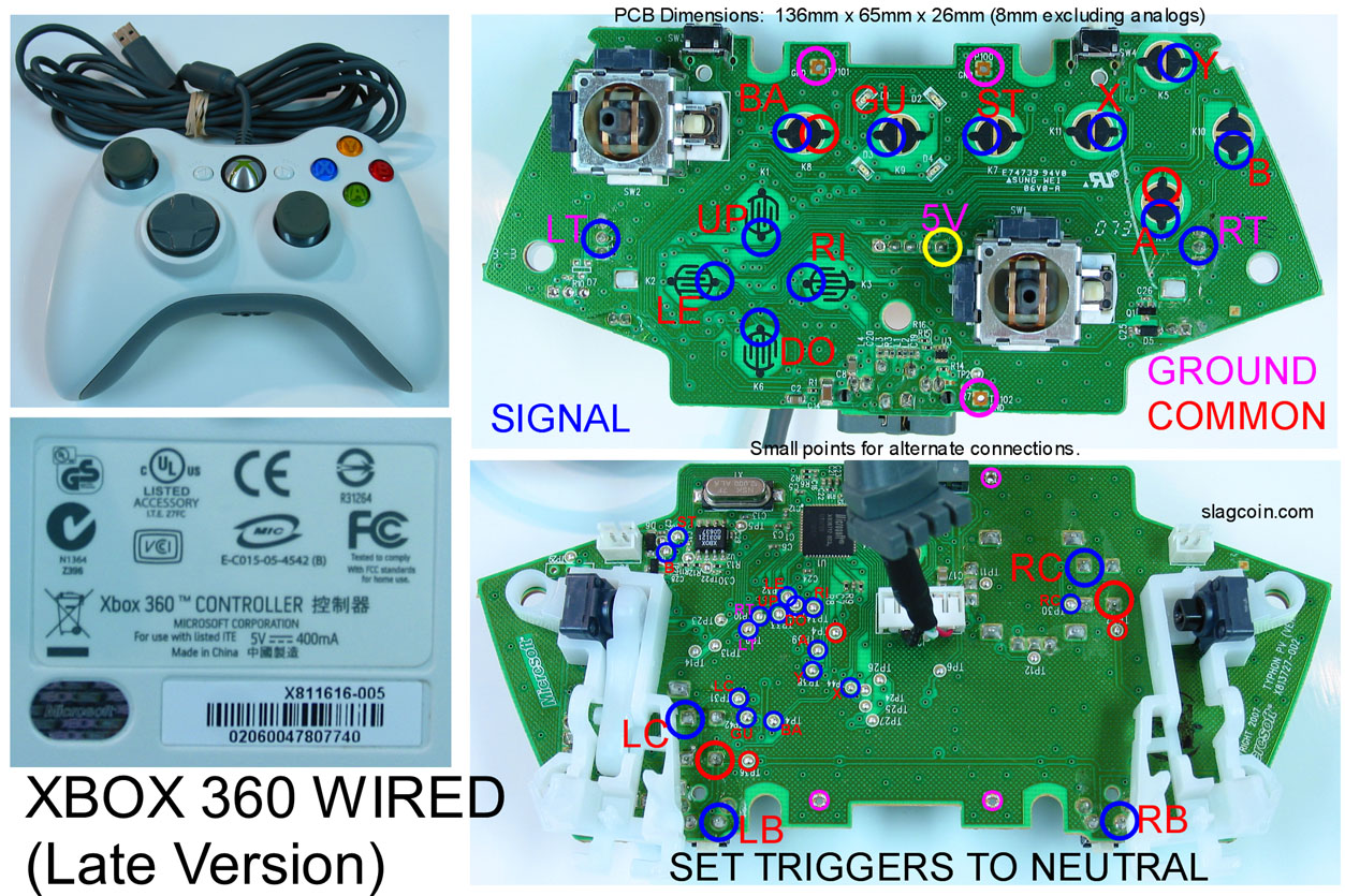
this is is my mswired controller, its the official one

http://www.ilovenicii.com/images/xbox.jpg

the back sticker is similar to the Late version posted online

heres what the pcb looks like,
some one give me a brief description on what to do,

do i have a common ground on my xbox pad ?
if so do i just take ground wire from each button and rainbow it on all 6 and stick last on to common ground?

http://ilovenicii.com/images/stick/b.jpg

http://ilovenicii.com/images/stick/c.jpg

http://ilovenicii.com/images/stick/d.jpg

http://ilovenicii.com/images/stick/a.jpg

http://ilovenicii.com/images/stick/e.jpg

http://ilovenicii.com/images/stick/f.jpg

bump

i dont know about your xbox360 pcb, but to check simply get a wire, cut two ends, plug up the pcb to your pc, and start linking the signals and a single ground together one by one to see if u get connection. if you cannot get any connection, your xbox360 pcb is not common ground. wire the signals to #1 on the hori pcb. if your xbox360 pcb is not common ground, daisy it up and feed that ground to an existing ground on the hori pcb.

and identical to the one slagcoin put up:

Its not a common ground, sorry. Common high, but that doesn’t really help here. MadCatz is still the only company that makes common ground pads that I know of.

thanks toodles/psychedelicbeat

but since its not common ground then how does the the diagram link apply?

basically now, for buttons, one to signal one to ground [i use multimeter to figure out which is which] and for diagonal i just need to know where to put the ground?

thats it i guess?

thanks again

Hey folks, hopping back in here because I had a few more questions about possible future mods.

First and foremost though, I’ve seen many responses such as “yes, that’s common ground” or “no, that’s not common ground”. (Usually by toodles) With these replies though, I still have no idea myself what exactly constitutes a common ground board. How can one tell for themselves if a board is common ground or not? (I’m mostly asking you Toodles, since you’re going off of sight here as far as i can tell)

Second question is a new idea on my part. While the digital pad PSX pcb worked great for my dual PCB mod (thanks again Shoryuken users. =D ) it was a rather messy mod (lots of loose wires) and there’s pretty much no room left in my fight stick if i wish to add another PCB ever. On that note, I got an idea from an old friend of mine who used to make custom DDR pads for folks.

Take the extra set of wires (ie all wires connecting to the 2nd PCB) for the buttons, stick, and +5 / GND and connect them to a plug (serial or parallel port perhaps?) or cord coming out of the stick. From here, I can connect said plug or cord to a small project box of my creation. Each project box would contain the PCB of a system I wanted to add support for. This would allow me to keep the base stick case somewhat nice and clean, and do all my work in each of these little “converter” project boxes. Long story short, a universal adapter for my joystick to any system I could make a project box for. (Out of a common ground PCB for said system)

The only possible problem i’m seeing is that travelling from the buttons to a PCB outside the box (ie a longer distance for the signal to travel through the wires) could cause a lag between button / stick presses and the console receiving this. I imagine that any possible lag would really be too small for a human to notice, but want to know if any of you think this would be a concern.

My last question involves adding a Dreamcast PCB to a stick. I was on Slagcoin’s site, and noticed a note by the Dreamcast PCB diagram : " (Lags) ". That said, I’ve seen light talk in this thread of adding Dreamcast support to sticks, but never any follow up replies by users. Are there any extra tricks for adding Dreamcast support, is it even possible? If so, any controllers that folks recommend using? (Since Toodles talked about Mad Catz making common ground controllers, I’m thinking a Mad Catz dreamcast controller might do the trick)

Thanks for your time, any and all who reply.

I can appreciate that; always best to learn than rely on someone else. Here’s what I’ve written previously on it.
http://forums.shoryuken.com/showthread.php?p=5027140&highlight=common+ground+multimeter#post5027140
http://forums.shoryuken.com/showthread.php?p=4726409&highlight=common+ground+multimeter#post4726409

Lots of folks have done project box setups, myself included.

Nope. Not even ‘really too small for a human to notice’, I mean NONE.

Use the PCB from an Agetec if you can. Super small, super easy to use, common ground, everything you could possibly want from a pcb.

Oh wow. Toodles, i can’t thank you enough for not only a swift, but also thorough response to each of my concerns. =D Thanks so much!

That said, seems like I’ll be having a new project to work on soon enough! ^^

Is the MadCatz gamepad (late I think) and the Gamestick for the 360 the only common ground pads I can use with a HRAP3?

You can add ‘PCB from inside a MadCatz SE or TE FightStick’ to the list, and I’m pretty sure (looks that way, but untested) that the pcb from a SF4 MadCatz FightPad would work, too. Otherwise, yeah, those are the only ones I know of.

Ah, OK. I was hoping for something a bit more obtainable. Thanks.

ok so has anyone done this dual pcb yet? how its work? does it cause any weird experiment or problem?