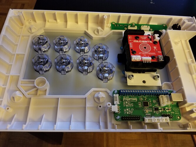
I have recently picked up a Qanba Q1 that I have decided to mod extensively. I have installed Paradise Arcades Magenta joystick in it, Gamerfinger buttons and because it was previously a Xbox stick I replaced the PCB inside with the Brook PS3/PS4 board. My question is I’m looking to use the buttons along the top of the stick (the ones that functioned as the mode, home, option buttons, etc) and just 1 of the LEDs to indicate mode changes on the joystick and can’t for the life of me find any diagrams online to help identify which pin is which for each of the buttons and LEDs and was wondering if someone here might be able to help?
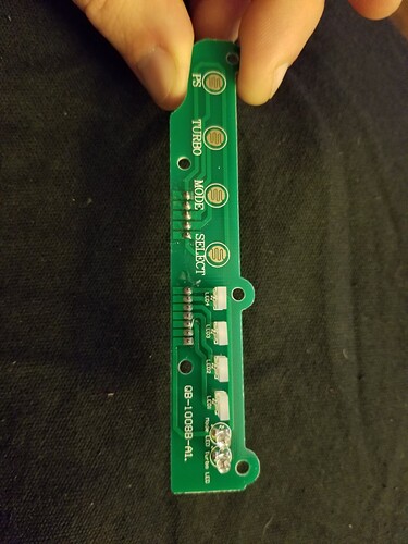
the 2 JST connections at the top are what I’m referring too (there seem to be a couple variants of the same stick, so I added the image to make things more clear) Any help would be greatly appreciated. Thanks in advanceUnscrew the PCB and you should be able to follow the traces pretty easily.
I don’t know the pinout off the top of my head, but if you took some clear pics of the front and back of the sub-PCB, I’m sure you’ll get the help you need.
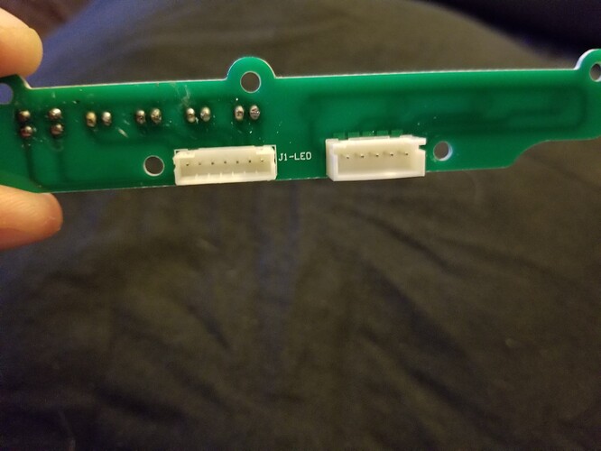
With both, I’m just having a hard time finding the pin that is ground and power leads. I’ve added images of both sides of the PCB as requested. Hopefully this helps me
On the second photo, with the back of the pcb, right pin is your GND for both connectors.
Then this is pretty much straight forward:
The 7-pin connector :
TurboLED / ModeLED / LED1 / LED2 / LED3 / LED4 / GND
The 5-pin connector:
SELECT / TURBO / MODE / SELECT / GND
Hey, I did that exact mod… https://imgur.com/a/ny1kN
^ that’s my album of all the changes I made over 3 years, this is how I wired that part specifically:


