where the hell do I solder to?!?! There aren’t any ‘convenient’ soldering points anywhere, other than the shoulder buttons and the ground.
Can I solder onto the black parts where the corresponding face / direction buttons are??? Do I need to scrape the black stuff off in order to reveal a more ‘shiny’ area to solder onto, or can I solder directly onto the black??
sambao: yea just scrape off the black stuff and solder. just make sure that the black stuff is completely off the part you gonna solder to.
i wouldnt recommend soldering to the legs if your not that comfortable soldering because you can bridge the legs with the solder easily. also you will have to find the pins for x, square, triangle, circle, r1, r2 because those go under the chip thingy. i have soldered one on my pcbs to the legs. its not that hard to me but i had previous experience modding my ps2. if you decide to go this route. you need 30 gauge wire. what i do is just tin the wire with just enough solder, place the wire over the pin, and press my iron(free of solder) on the wire for just a sec.
the website above was posted by bustawolfe a couple posts below and it has it hacked. you can see that he just scraped it off. for the the buttons he labeled B1-B6, i would recommend scraping the end part of the black bridge. for instance, for b3 he solder to the point he circle, but i would scrape the opposite end of that. although his circled points should have not problem at all.
i use a small slotted screwdriver, the 1.4 mm to be exact. anything along those lines will get the job done such as razor blades, tip of a knife… after that i just sand it or use an eraser to remove the oxidation on the copper that is exposed. dont be scared to use some force to get the black shit off as you will most likely NOT ruin the pcb in any way.
i used one of those pcb’s before and they are very durable. i used a razor to scrape mine. its not gonna damage the pcb, there is copper under there. but you should still be careful, better safe than sorry.
k this is the first time im doing the nonsoldering method and i was taking a look at where the ribbon was and i have to say those points look mighty close. wouldnt the wires hit each other?
Hi everyone
I have a ps1 dualshock pad the same one that kbtoyz902 has a picture of here is the link: http://i18.tinypic.com/4d1v974.jpg
But can anyone please help me with the layout? wich is up, down, left, right, square, traingle, circle, X, start, select, and the (common) ground? And besides is it fairly easy to solder on?
I know this question has been asked previously, but i couldnt find anything on the net so i ask this favour here. Is there someone who can help me out?
help is very much appreciated.
Thanx in advance
I dont know the exact answer for yours, but I found with mine I just plugged it into my comptuer with the USB adapter, and started to just test each one.
That way i knew for sure, rather assuming that some guide out there was right. (for my ps1 dual shock that is, my wireless pad was amazingly simpler)
uhh, just put a game in like 3s to test which spot corresponds to what button. since the ps1 ds have one common ground, you could test each pin by taking a wire and touch one end of it a pin and the other end to a ground. an easy ground you can touch it is where the black wire was where the motor was taken off
the links of the first page dont seem to work, i was wondering if someone else had usefull links where it would tell u the solder points. i also wanted to know if anyone had specd/dimentions to making ur own arcade stick, and where would i get the wood? homedepot i guess? does anyone know how to remove the top cover of the hrap1 (mirror front)?
Thanx a lot you guys, now i have a much better understanding how to solve the problem. But i still have 2 more questions, then i’m ready to go for building my first custom stick.
#1- In order to test wich is wich button and direction, do i need to get rid of all the wiring including that of the wiring from the “shock motors”, except the insert cable to a ps2. In other words whats left is the pcb and the cable to connect to the ps2?
#2- When i made my custom stick, is it possible to change the BUTTON CONFIG? For example R1=HP but i want it to switch to MP. Or L2 for burst (GG slash).
Removing the rumble motors is a good idea. It sounds like you have the right idea.
Every PS2 fighter worth a damn supports button mapping, so you’re concern should be adapter compatibility; stop thinking in terms of HP or dust, and think in terms of X, O, [] and /. Stick to the normal layout; top row: [] /\ R1 bottom row X, O, R2
This will give you the best adapter compatibility, and matches the layout in the majority of games, since it matches the majority of sticks manufactured since the dawn of time.
Thanx again for the quick reply guys. Like you said UltraDavid; If it’s a custom stick you made, why don’t you just rewire the wires to the buttons you want? So if i got it right you have to make sure what kind of button lay out you want, before making a custom stick. The thing is i dont use 1 type of layout for all of my fighting games. So its necessary for me to change the button config, and that depends wich fighting game i play. I know this may seem strange but it’s crucial. Now i have the idea you can’t change the button config when using a custom made stick or am i wrong? hope i’m wrong…
That’s cool. You can definitely change the button configuration in-game, hooking up buttons and a joystick to a Playstation pad doesn’t remove that capability.
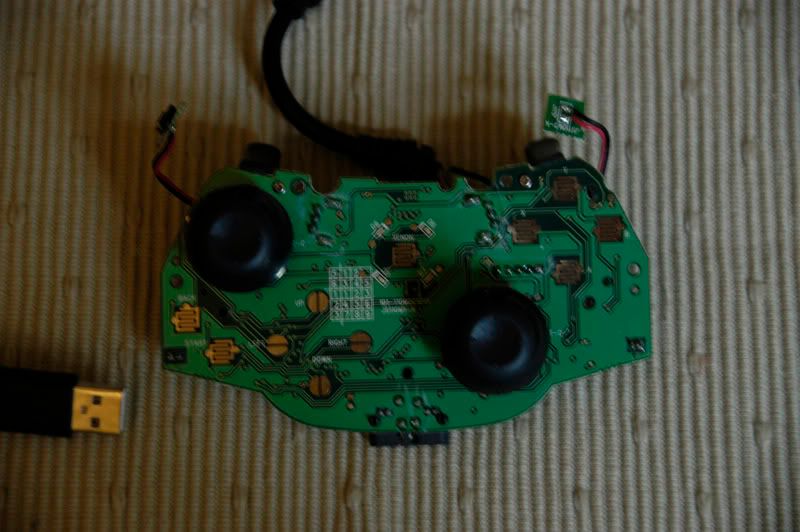
This might be of help to somebody. I hacked a Logitech Neo SE Advanced controller for the XBox 360 today, so I took a pic before I started:
Sorry about the focus, I didn’t check it until later, by which point it was all soldered up, you can probably make out what you need to see though.
I picked this one up as a) it was cheap and b) I hoped the solder points for the d-pad would be easier than on an official pad. They certainly were, but the buttons were harder! Overall it was probably easier though, so something to consider if anyone else is trying an XBox 360 stick!
Just to let you guys know, I don’t know if i fried my pcb or not but once it’s wired it works for a good 5 minutes then it just flips out and keeps on jumping up. It’s not a connection problem because it’s almost like clockwork that it’ll flip out after a few minutes. Or maybe the pcb is not that simple to hack. I even disconnected all my wires and it keeps on jumping.
I’ve abandoned that pad and am going for the Series H hack.
To be continued…
P.S. I’ve had some experience with hacking the Nyko Dreammaster until the wires became loose and the copper connections faded. Worked for a solid 2 years then it just died :wonder: