Legacy support doesn’t work with this controller out of the box unfortunately. ):
Is this still the non-common ground, wireless 360 pad you’re talking about? I believe soldering to the joystick is the only way to get it to work. JST harness is most likely a no go. I’m no expert, but I had to do this when I modded the original, original Mayflash. Cut the traces, then soldered directly to the microswitches.
No, this is a common ground one.
I’ve noticed, it works fine when the USB cable from the mayflash pcb is plugged into a device.
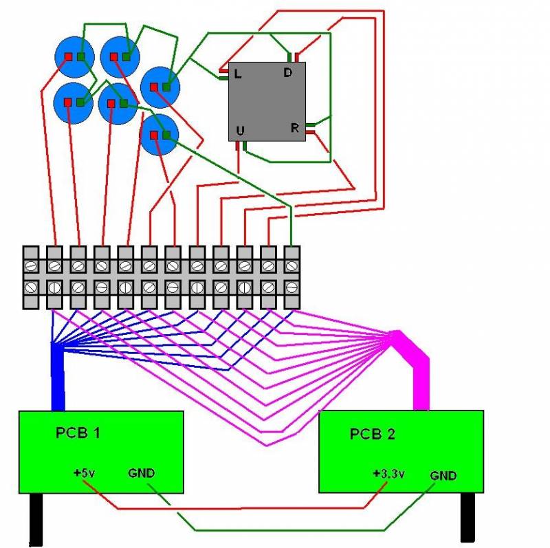
Is it because I did not connect the V from each others pcb like here?
Edit: Yes, it is because of the V!
Is it really okay to solder 3.3V from the xbox pcb to the 5V on the mayflash pcb? Without any issues if I plug in the USB cable later on? http://i.imgur.com/cyshRDq.jpg
@deserada, I need more clarification. In our convo above, you mention buffing compound, but in the Google+ tutorial, you mention rubbing compound for the plexi. Which one is it or did you use both? xP Also can you say which brand you used if possible? Thanks?
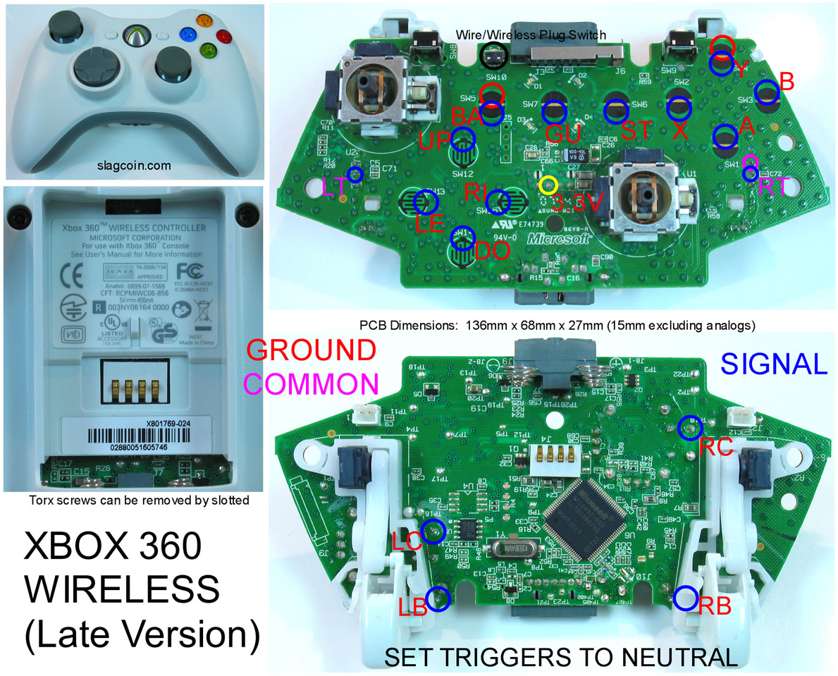
I’m asking because after soldering the common ground xbox 360 PCB 3.3V line to the 5/RED the mayflash pcb didnt want to recognize the joystick input anymore, while the x360 recognized the joystick input just fine.
Yes there’s a 360 PCB as a dual mod.
The 3.3v line is on the 360 PCB: http://www.slagcoin.com/joystick/pcb_diagrams/360_diagram7.jpg
Sanwa lever is connected to Mayflash PCB with a JST-XH Female to Female connector.
I’ve soldered the x360 pcb dpad like this to the Sanwa lever/back of the mayflash pcb:
When I solder the 3.3v from the x360 pcb to the 4/White (5/Red has whacky input??) everything works on the x360 pcb
When I remove it everything works on mayflash pcb but obviously not on the x360.
A switch would fix that but is there any other way get around a switch?
edit2: no one that did a wireless dual mod with this pcb/stick?
@shadoom I’m not sure why you are using a 3.3V line on the 360 PCB. You power that PCB by giving it the same 5V and ground that the Mayflash is getting over its USB connector.
Thank you for the referenced post, the 5V line did not do anything somehow… but(!)… I used the GND from that post and the 3.3V line I have on the front and now everything works!!
Thanks a lot again deserada, you’re my hero for this week <3
Hi all
I’ve the Mayflash v2 since few weeks, but i will like modding him.
For make a recap of parts
I think put the Sanwa buttons OBSF24 and 30 because, it’s works without modifs, it’s right ?
For the joystisk, i prefer put a LS32-01 (or other Seimitsu reference ?), if it’s works without modifs also
I must add other parts ? specific cable and plate or it’s with the joystick ?
@Roghin
The JST cable you can buy in order to connect a lever without soldering only works for Sanwa levers. The header on Seimitsu levers has a different pinout. If you can solder, you can either modify the cable or solder the lever in directly. You could also cut traces and rewire the Seimitsu lever’s PCB. It’s up to you.
The easiest way to get a Seimitsu lever in this stick is to solder it directly, or to add quick disconnect spades and connect them to the switches on a Seimitsu lever without a PCB (pins to connect to a harness).
@Roghin
This looks like the right cable for the lever:
You can try using a terminal block, but with this cable you can plug directly into the PCB. I just double checked, and in order to connect to a Seimitsu lever, you would just plug the cable into the lever’s header upside down (try the other orientation if the other does not work). I was wrong about needing to cut traces, so that saves some work.
Just so you know as well Focus attack sell’s this for and it will work if your installing the Sanwa JLF or Seimitsu LS Series., https://www.focusattack.com/spare-5-pin-female-harness-for-zero-delay-usb-encoder-pcb/ I just opened my stick and i had a jlf laying around noticed i needed a female header. i dont have it yet, but i ordered 4 of them lol and in the descritpion it says it will work.

